Custom Headlight Reflector Injection Mold
Analysis of plastic parts for automobile headlight reflectors
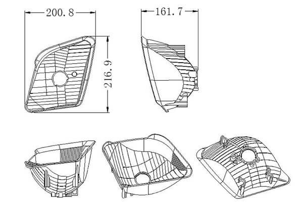
The picture is a part diagram of a certain brand of automobile headlight reflector, the material is BMC, which is a thermosetting plastic. The material is an extra-hard material, and the shrinkage rate is almost zero, so there is no need to adjust the shrinkage rate during mold design. Because it is a super hard plastic, it has the advantages of high dimensional accuracy and good processing performance, but the disadvantage is that it has poor fluidity. The outer surface of the plastic part needs to be electroplated (generally aluminum-plated), and the plastic part is an appearance part with high requirements on the surface.
The size of the plastic part is: 216.9×200.8×161.7mm. The structural characteristics of plastic parts are as follows:
- 1. The appearance surface demands are exceptionally stringent, prohibiting any blemishes or gate marks, as well as flaws like shrinkage depressions, welding marks, and protruding edges.
- 2. The plastic parts are electroplated parts, which have strict light distribution requirements, and the exterior surface is plated with aluminum. The design of the demoulding slope of the exterior surface should be reasonable, and generally at least 5° must be guaranteed.
- 3. The plastic part boasts a sophisticated shape and demands a polished surface finish. There are no undercuts on the interior or exterior, and lateral core pulling is unnecessary. Additionally, the plastic part is a mirrored image of itself, both left and right.
BMC injection molding process for car headlight reflector
The process involves introducing refrigerated BMC material into an injection molding machine barrel specifically designed for BMC material. The screw’s rotation generates shear heat, melting the material at a lower temperature (25 degrees Celsius). The viscous, gelatinous material is then injected under high pressure and preheated to 140-160 degrees Celsius within the mold. Under the action of high temperature, the chemical reaction is carried out, and after the pressure is maintained, it is solidified and formed, and the mold is opened to take out the molded plastic part. Finally, the burrs and debris in the cavity are blown away with an air gun, and the mold is closed for the next cycle.
Structural analysis of automobile mold
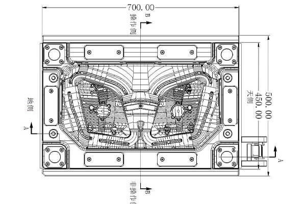
The car headlight reflector is a mirrored image of itself, both left and right. The steel mold has 1+1 cavities and uses a cold runner casting system.There is no undercut on the inner and outer sides of this plastic part, so there is no lateral core-pulling mechanism. The overall dimensions of the mold are: 700×500×568 (mm), and the total weight is about 1 ton, which belongs to the medium-sized injection mold.
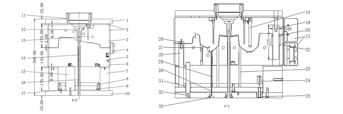
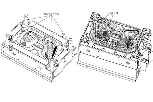
The names of the components in the above picture: 1. Panel; 2. Heat insulation board; 3. A board; 4. Lock module; ;9. Push rod bottom plate; 10. Bottom plate; 11. Positioning ring; 12. Nozzle; 13. Temperature needle; 14. Push tube needle; 15. Support column; 16. Push tube; Heating tube 19. Guide column; 20. Pressure plate; 21. Junction box protection block; 22. Guide sleeve; 23. Push rod; 24. Limit block; Insert; 28. Reset lever; 29. Push tube sleeve; 30. Push tube needle; 31. Push rod plate guide sleeve; 32. Push rod plate guide column; 33. Push tube needle pressure block;
The three pictures are the mold structure diagram of the car headlight reflector. While sharing a basic structure with thermoplastic injection molds, there are several distinct differences and notable characteristics that set it apart.
1.The core is located in the moving mold base.
Generally, the mold cavity is set in the fixed mold, and the core is set in the movable mold. Since the core of the mirror plastic part is a multi-curved surface reflecting and concentrating working surface, which requires very low roughness, it is absolutely impossible to install ejection devices such as push rods, so the mold must be made upside down, that is, the protruding core (mirror work Surface) is set in the fixed mold, and the recessed cavity is set in the movable mold.
2. The mold needs heating tube heating and strict temperature control.
The injection molding process for BMC materials differs significantly from the standard thermoplastic injection molding process. The cylinder part of the injection molding machine needs to be cooled by a special refrigerator with ice water, while the core of the mold cavity needs electric heating.
The total power W of the electric heating tube required for the fixed and movable mold can be calculated by the following formula:
W=Gcp(Tm-To)/3600yt
G: Total weight of fixed and movable molds, kg
cp: mold material specific heat capacity, kj/(kg.°C)
Tm: Temperature required for mold forming: °C
To: Room temperature: °C
y: Heater efficiency, take 0.3-0.5
t: heating time, h.
The diameter of the electric heating tube generally used is 15.8mm, which can quickly increase the mold temperature. According to experience, the mold heating power can be calculated according to (40-50) W/kg. The molding surface of the plastic part is 40-50mm away from the electric heating tube, and the distance between the two electric heating tubes is 80-100mm. In order to improve the heating efficiency, an 8mm thick bakelite heat insulation board should be designed on all four sides of the fixed and movable mold. Because the electric heating tube has no positive and negative poles, it can be connected in series, but each group of thermostat sockets should not exceed 3.6KW. The temperature of each group of electric heating tubes is controlled by a group of thermocouples. For precise temperature control, it is important to position the thermocouple at the center of the temperature field of the electric heating tubes in this group. Additionally, the thermocouple head should be in direct contact with the cavity to ensure effective measurement.
3. The runner system of the mold needs to be temperature controlled.
The thermosetting injection molded material will undergo a chemical crosslinking reaction and solidify when it exceeds a certain temperature. The solidified gating system aggregate cannot be recycled and can only be treated as waste. Using a runner that does not allow for condensate from the pouring system is highly significant. The sprue sleeve of the mold needs to be cooled by cold water. In order to reduce excessive shear heat during the injection molding process, increase the injection molding speed, and prevent the molten BMC material from solidifying before filling the high-temperature cavity, fan-shaped runners are usually set up on the movable mold, and the thickness of the gate is 2.0-2.5mm.
4. Requirements for mold parting surface
BMC materials have a lower viscosity than thermoplastics. No holes or dimples are allowed on the parting surface. Slider locking blocks, pressing blocks, etc. are not allowed to be set at the mold core, otherwise it will cause difficulty in flash cleaning.
5. Strengthen the exhaust of the mold cavity
Thermoplastic molding is a process that involves physical changes, whereas injection molding of thermosetting plastics involves a chemical reaction process. Large quantities of volatile gases are generated during chemical reactions. The resistance of these gases to injection molding is significant, leading to the formation of bubbles and insufficient material on the plastic parts’ surface. Additionally, the compression of the gas generates high-temperature charred plastic parts. Consequently, proper ventilation of the thermosetting injection molding mold cavity is crucial. Generally, the parting surface of the mold and the bottom of the fixed and movable mold inserts need to be equipped with high temperature resistant sealing rings. Vacuuming is used at the end of the fixed mold cavity to overcome molding defects. It is also convenient to increase the injection speed.
6. High precision of plastic parts
The light distribution requirements of car light reflectors are extremely high, and the roughness of the reflective surface of the mold, processing and assembly accuracy are extremely high. In addition to the mold base lock and guide post positioning, the mold core also needs to be designed to ensure the three-level positioning of the mold is reliable. The area of the light distribution pattern of the polyhedron of the reflector is small and cannot be polished by hand, so a precision five-axis high-speed CNC machining machine must be used. The spindle speed of the machine tool reaches more than 20,000 revolutions per minute. Employing state-of-the-art CAM technology and specialized tools, select a suitable processing technique to accomplish one-time processing accurately.The precision of the cavity is required to be 0.01-0.02mm, and the surface roughness of the cavity is 0.05-0.10 microns.
Injection Molded part design
The molded parts and templates of this mold adopt integral type. Compared with the split structure, it has the advantages of compact structure, good strength and rigidity, and avoids cumbersome processes such as frame opening, frame matching and wedge manufacturing.
The inner surface of the headlight reflector has high requirements, and the roughness is small, and thimbles and inlay traces are not allowed, so it must be formed by a fixed mold. The outer surface has relatively low requirements and is formed by the moving mold part.
As one of the most crucial exterior components of a car, this plastic part possesses a high-gloss finish and necessitates vacuum plating on its surface. During the mold design process, careful consideration must be given to the selection of appropriate mold materials. Due to the poor fluidity of the BMC material, overflow grooves need to be designed around the movable template cavity, and push rods need to be designed at the bottom of the overflow groove to facilitate the ejection of the overflow.
The mold used for BMC thermosetting material that’s infused with glass fiber should possess superior wear resistance, hot red hardness, and thermal fatigue resistance. To meet the mirror’s stringent light distribution criteria, the core must exhibit superior polishing capabilities. Thus, the fixed mold is crafted using German 2344ESR hot work tool steel, which boasts exceptional hardenability and quenching hardness of 48-52HRC. The steel material is subjected to vacuum electroslag remelting, which enhances its crystal uniformity and promotes excellent polishing results. After hard chrome plating, the fixed mold undergoes frequent polishing to minimize surface roughness, enhance wear resistance, and prevent corrosion. The material of the moving mold and the insert of the moving mold is made of German 2344HT hot work tool steel, with a quenching hardness of 48-52HRC.
The penetration angle of the inserting part of the fixed and movable molds of the mold is guaranteed to be at least 7 degrees. In order to ensure the precise positioning of the fixed and movable molds, the fixed and movable molds of this mold adopt four-corner spigots and four sides for positioning. Due to the precise positioning of the insertion point, the fixed and movable molds need to be tightly matched during mold fitting. For the sake of mold beauty and mold matching, a 5-degree wear-resistant block is designed on the fixed mold. At the same time, the design of the wear-resistant block is convenient for the fitter to match the mold and ensures the beauty of the mold.
The mold design also achieved the following points:
- 1.The parting surface should have a smooth finish without any sharp corners, and there should be no usage of thin steel, wire, or point sealant. The surface sealant is constructed, and the method of extending, sweeping, and grid is used to make the surface when parting the mold. The parting is based on the shape of the plastic part Shape construction surface. The parting surface of the car lamp mold is extremely demanding, and the surface to be constructed is not allowed to wrinkle. The constructed parting surface can effectively guarantee the machining accuracy of CNC, without the need for EDM to clean the corners, and the parting surface is not easy to run burrs. A high-speed machine is required for the light knife on the parting surface of the lamp mold, and the spindle speed of the machine tool must be guaranteed to be at least 20,000 revolutions per minute.
- 2. The matching part of the insert and the moving mold. The root of the spigot is designed with a suitable process chamfering R angle or an avoidance position, which simplifies the processing procedure and reduces the processing time, and improves the processing efficiency.
- 3. All non-formed corners are designed with R angles. In order to avoid stress cracking, the R angle used in the process must be greater than or equal to R5. According to the size of the mold, design a relatively large process R angle as much as possible. The sharp edges on the mold can easily cause accidental injury to the operator. Edges on the mold that do not participate in forming or matching must be designed with C or R angles. According to the size of the mold, design a relatively large chamfer as much as possible.
- 4.Avoidance of the parting surface. The width of the parting surface of the mold is 40MM, and the fixed and movable molds in the area outside the parting surface must avoid 1MM to effectively reduce the processing hours. Parting surface avoidance not only refers to the peripheral parting surface, but also includes large-area parting surfaces. Special Note: The width of the parting surface of the mold includes the exhaust groove. A pressure-bearing block should be designed in a large-area shelter to ensure that the mold is evenly stressed and avoid long-term production of the mold. While avoiding air in the area of the collision hole, it is also necessary to design vent holes in the fixed mold or the movable mold to facilitate the discharge of compressed air when the fixed and movable molds are closed.
- 5.The parting surface is constructed according to the shape of the plastic part, and the plastic part is optimized if necessary. To make CNC machining easier, it is recommended to widen the bearing plate groove as much as possible for molds of medium and large sizes. When designing the parting surface, try to simplify the mold processing and make it smooth and smooth. The parting surface made has no thin steel, no sharp corners, and the insertion angle is reasonable.
- 6. The parting surface is smooth and smooth. When UG parting, it is forbidden to have a lot of small broken surfaces (it is easy to bounce the knife during CNC machining, and the machining accuracy is reduced), and try to use the extension surface, mesh surface, and sweep surface to build the parting surface. Or extend the sealing surface by 10-20mm first, and then make the stretching surface and transition surface. The sealing surface is designed according to the tonnage of the injection molding machine and the size of the mold.
- 7. All insertion angles of the parting surface or the insertion hole are designed to be above 7 degrees to improve the service life of the mold.
Design of gating system
The mold gating system adopts “ordinary runner + fan gate”. Since the plastic part is made of BMC material and has poor fluidity, the flow channel should be thick and short when designing the flow channel. In order to reduce excessive shear heat during the injection molding process, increase the injection molding speed, and prevent the molten BMC material from solidifying before filling the high-temperature cavity, fan-shaped runners are usually set up on the movable mold, and the thickness of the gate is 2.0-2.5mm.
Design of temperature control system
The automotive headlight reflector is a crucial exterior component of a car, and it also has some of the most stringent appearance standards of any plastic part. Therefore, the design of the temperature control system has a great influence on the molding cycle of the mold and the quality of the product. Because the plastic part is composed of BMC material, the injection molding process for BMC is fundamentally distinct from standard thermoplastic injection molding processes. The cylinder part of the injection molding machine needs to be cooled with ice water by a special refrigerator, while the core of the mold cavity needs electric heating.
The layout of the heating pipes is similar to that of waterways, similar to that of water wells, and can be designed either vertically or horizontally. To enhance heating efficiency, an 8mm-thick bakelite heat insulation board should be created on all four sides of the fixed and movable mold. The molding surface of the plastic component should be situated 40-50mm from the electric heating tube, and the space between the two electric heating tubes should be 80-100mm. The electric heating tubes do not have positive or negative poles, so they can be connected in series. However, each thermostat socket set should not surpass 3.6KW. A group of thermocouples controls the temperature of each group of electric heating tubes. The thermocouples should be in the center of the temperature field of the group of electric heating tubes, and the thermocouple heads must be in effective contact with the cavity, which is conducive to accurate temperature control.
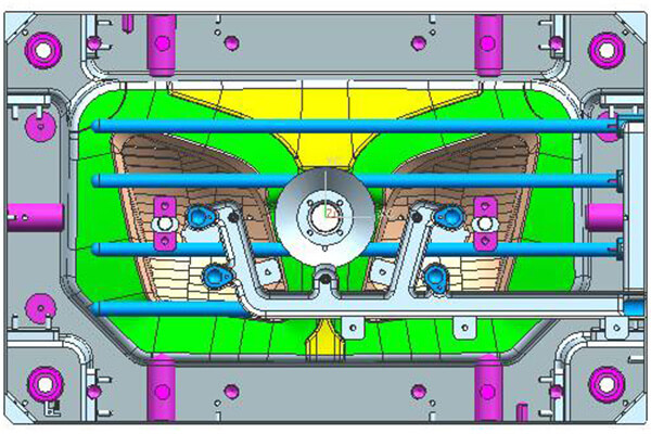
The temperature control system of the fixed and movable molds of the mold is as follows: 2 vertical heating pipes are designed for each cavity of the fixed mold, and 4 horizontal heating pipes are set for the fixed mold. Each cavity of the moving mold is equipped with three vertical heating tubes and two horizontal heating tubes. When arranging the heating pipes, pay attention to the wire slots. The corners of the wire slots need to be rounded to avoid damage to the wires. A temperature probe should be designed for each mold, and the heating tubes should be spaced evenly. The heating tubes need to be ordered from the supplier. The heating tube hole should be 1mm larger than the heating tube, and the depth should be 1mm deeper, because it will expand when heated.
Design of guidance and positioning system
One D40*225 round guide column is designed on each of the four corners of this mold. (The longest guide post is 10 times the diameter) The guide post is installed on the fixed mold side. Since the plastic part stays on the movable mold side after the mold is opened, this will not affect the removal of the plastic part, and at the same time prevent the plastic part from sticking to the guide post.
The guide post can also be used as a supporting foot when turning over the mold, which is convenient for the FIT mold. The length of the circular guide post must ensure that when the mold is closed, the guide sleeve should be inserted 20mm before the inclined guide post is inserted into the slider, otherwise it will cause great trouble in the manufacture and production of the mold, and in severe cases, the mold will be damaged. The design of the mold guiding system must pay attention to the design of the three-level positioning, especially the demanding automotive plastic parts. Unreasonable mold guide positioning design will cause problems such as unsmooth mold movement, easy damage to the mold, misalignment of fixed and movable molds, and step differences in plastic parts. It is a crucial system for injection molds.
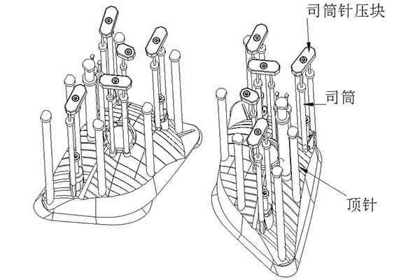
Design of demoulding system
The ejection structure of this mold is ejector pin (that is, push rod). After the fixed and movable molds are opened, the mold relies on the push rod to push out the plastic parts and runner aggregate. The ejector rods are connected together, and pushers such as ejector pins and reset rods are pushed out and pulled back by the ejector rods of the injection molding machine. There is no need to add back-moving springs next to the 4 back-moving rods, but a reset block 26 will be designed at the fixed template position in contact with it, the material is S50C, and the surface is nitrided.
When designing the mold release system, the following points should be paid attention to:
- 1. The guide column of the push rod plate should be arranged near the push-out element with large push-out force (such as oil cylinder, reset rod, etc.).
- 2. All automotive injection molds need to be designed with a limit column, and the limit column should be placed above or near the K.O hole first.
- 3. The push rods should be arranged at the force-bearing position close to R, and arranged at the position where the tightness is large. To achieve ejection balance in BMC thermosetting materials, it is important to have a design specification for push rods that is both large and includes a large number of push rods. This is because the plastic part of BMC is very hard, and it has a large holding force to the mold, and requires a large ejection force.
- 4. Designing push rods with the same diameter specification can help avoid frequent replacement of drill bits and ultimately save processing time and costs.
- 5. All push rods with special-shaped surfaces must be designed to prevent rotation to avoid incorrect assembly, and the surface of the push rod has a grid to avoid slipping when the push rod is ejected.
- 6. The design of the back needle hole has a space avoidance on one side (0.5 for small and medium-sized molds, and 1.0 for large molds), and a craft screw hole is designed at the end of the return needle. To facilitate processing and mold closing, it is recommended to design a return block on the face of the return needle when the needle’s diameter is 20MM or greater. The ejection hole of the injection molding machine equipment cannot interfere with the garbage nails and support columns.
Design of mold base structural parts
The mold is guided and supported by 4 D40*225 guide pillars, and the overall strength of the mold is good. During the injection molding process, due to the influence of the injection pressure, the strength of the template will be affected to a certain extent. Therefore, in addition to sufficient mold base strength, it is also necessary to design some auxiliary structural parts to enhance the strength and life of the mold.
When designing, it is important to pay attention to the following points:
- 1. To facilitate FIT mold and processing, ensure that the mold is designed with four process screws between the thimble bottom plate and the code template. The specifications of the process screws are one size larger than the thimble plate screws. The process screws are to be removed during the mold production, the purpose of this design is to facilitate the identification of the fitter and prevent mistakes. The limit column should be arranged above or near the KO hole as far as possible, and more garbage nails should be arranged at or near the bottom of the inclined roof and straight roof, with a spacing of about 150mm.
- 2. The pressure block on the parting surface of the mold sinks into the mold, the oil groove cannot be opened on the pressure block and the fine positioning, and the distance between the pressure block groove and the edge of the mold frame must be at least 15mm.
- 3. The design of the limit column: the mold for mechanical ejection is designed above the hole of the ejector stick; the mold for cylinder ejection is designed above or near the oil cylinder.
- 4. Design of supporting columns: The gap between supporting columns and square iron should be within 25-30mm, while the gap between the supporting columns themselves should range between 80-120mm. Additionally, the combined area of all support columns should be around 25%-30% of the area covered by the push rod fixing plate. 1. Design more supporting columns in the area where the glue is fed and the projected area of the plastic parts, and the supporting columns should be designed as large as possible. Because the injection pressure in these areas is concentrated, the parting surface is prone to flash, so designing more support columns can reduce the generation of parting surface and runner flash. 2. Arrange braces at the hollowed out position of the mold, where the strength is weak, such as the bottom of the slider, the bottom of the inner core, etc.
- 5. To prevent the ejector plate from deforming, it is necessary to design fastening screws near the return needles when the ejector system consists of two plates. Additionally, the garbage nails should be designed on the bottom plate at the bottom of the return needles.
Mold working process
The melt passes through the nozzle of the injection molding machine, and enters the cavity of the mold through the nozzle 12. After the melt fills the cavity, it is kept under pressure, cooled and solidified, and when it is sufficiently rigid, the injection molding machine pulls the movable mold fixing plate 10 of the mold, and the mold is separated from the mold. The mold is opened at the surface PLⅠ. After the mold is opened for 300mm, the oil cylinder of the injection molding machine pushes the push piece fixing plate 8, and the push piece fixing plate pushes the push rod 28, and then the injection molding machine oil cylinder continues to work, and after the ejection is 70mm, the plastic part is separated from the movable mold, and the plastic part is picked up by the manipulator , the oil cylinder of the injection molding machine pulls the pusher and its fixed plate to reset, and then the injection molding machine pushes the movable mold to close the mold, and the mold starts the next injection molding.
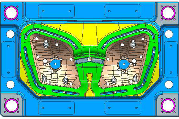
Mold strength and parting surface pipe position design
The pipe position of the parting surface of the mold is designed on the fixed mold, and the design form of the combination of the four-corner spigot and the four-sided edge is adopted, so that the positioning is reliable and the mold strength is good. In the design of automobile molds, the angle of insertion of fixed and movable molds should be designed to be more than 7 degrees as much as possible, and it should be designed to be more than 5 degrees if it is not possible. Because the insertion angle is large, the life of the mold will be greatly improved, and the phenomenon of the front of the mold insertion will be greatly reduced. For the position where the insertion angle is below 3 degrees, it is difficult to ensure the precise positioning of the fixed and movable molds with 1-degree precise positioning and 0-degree precise positioning, so the insertion angle should be as large as possible. For large and medium-sized molds, it is generally designed to be above 7 degrees. So as to ensure the service life of the mold.
The main dimensions that affect mold strength and rigidity include:
- 1. Dimensions A1, A2, B1 and B2 from the edge of the cavity to the edge of the mold.
- 2.The distances C1 and C2 from the deepest part of the cavity to the bottom surface of the fixed template and the movable template.
In the design of automobile molds, the empirical method for determining the dimensions of A and B is:
- 1. If there is no lateral core-pulling mechanism, add 30 to 50 mm from the outermost edge of the cavity to the sealing size (30 mm for small molds within 5050, 40 mm for medium molds of 5050 to 1010, and 50 mm for large molds above 1010), Add another 50-70mm space to reduce the workload of mold matching. The void is also an area that ensures the strength of the mold. Then add the size of the parting surface pressure plate at the formwork to be the size of A and B.
- 2. If there is a lateral core-pulling mechanism, the dimensions A and B must be increased according to the core-pulling distance. In principle, it must be ensured that the slider still stays in the formwork after the core-pulling is completed.
The value of the mold dimension C will be different for plastic parts of different sizes and structures. The dimension C must ensure that the steel thickness from the deepest part of the cavity to the bottom surface of the formwork is more than 80mm. In the movable formwork, since the space between the two square irons is empty, it can bear It is easy to deform after injection pressure, so the thickness of C1 needs to be increased accordingly, generally more than 100mm.
Since this mold has two molds, the two cavities are left and right symmetrical, A1=A2=115.6mm, and the distance between the cavity of the left reflector and the right reflector is 73mm. Since the mold has no lateral core-pulling mechanism, B1=123.1mm, B2=110mm. In terms of thickness, C1=103mm, C2=80mm, the B board is thinner, try to design it around 100mm.
Mold exhaust system and discharge design
The exhaust of thermosetting injection molding mold cavity is particularly important. Generally, the parting surface of the mold and the bottom of the fixed and movable mold inserts need to be equipped with a high-temperature resistant sealing ring, and a vacuum is used at the end of the material flow of the fixed mold cavity to overcome molding defects. At the same time, it is also convenient to increase the injection speed. The movable mold of this mold uses inserts, and the gap between the insert pin and the movable mold is exhausted. The fluidity of BMC is poor, and overflow grooves need to be designed around the movable model cavity, and ejector pins need to be designed at the bottom of the overflow groove to facilitate the ejection of the overflow.
Results and Discussion
For automotive lamp reflector molds, the main design points are:
- 1. Special injection molding process equipment is required, and an injection molding machine dedicated to the production of BMC plastics is required. The requirements for injection molding process equipment are very strict.
- 2. The BMC material is an extra-hard plastic. In the mold design, it is necessary to design a heating system and a parting surface design discharge system. The molded parts must be quenched to improve wear resistance and mold life.
- 3. The reflector plastic part is a device to prevent direct light on the car lights, reflect the light and avoid direct light, and the light distribution requirements are strict. Plastic parts are the most important exterior parts of automobiles, and there are many patterns on the surface of plastic parts for decorative and aesthetic purposes.
- 4. The ejection system of the mold design for BMC materials should be balanced, and the specifications of the push rods should be designed as large as possible, and the number should be as large as possible, otherwise it will cause difficulty in demoulding the plastic parts.
- 5. Because the demoulding slope of the high-gloss plating part is too small, it will cause difficulty in demoulding, so the side wall of the mirror plastic part should be designed as large as possible, and it is generally recommended to be 5°~10°. Of course, the premise is that the function and shape of the plastic parts cannot be affected.
- 6. Plastic parts cannot have sharp corners and sharp edges, and all corners need to be designed as rounded corners, because the formed parts of the mold are prone to stress cracking after quenching.
- 7. Note that the lamp head hole of the left and right reflectors and the pattern on the surface of the plastic part are translated left and right, and cannot be designed as mirror symmetry, because the bulb and the lamp holder will not be separated from the left and right, and the rest of the features are mirror symmetry.

About Sungplastic
Sungplastic is a plastic product manufacturer with rich experience in injection molding. According to the different product development requirements, we flexibly adjust the manufacturing process to achieve high quality, high efficiency and more economical.
We offer a variety of manufacturing services: Rapid Prototyping, Tool Making, Injection Molding, Product Design and Development, CNC Machining and Metal Stamping. You can choose from a variety of plastics, silicone rubber, or metal for your product. Regardless of mass production or small batch customization, Sungplastic has always been committed to providing assured, efficient and more economical one-stop processing services for your projects.
Contact us for a free quote and project review.


Get a free quote and design analysis today.
We’ll reply to you within 6 working hours.
We respect your privacy.
+86 139 2927 4777 (WhatsApp, Wechat)