Injection Mold Design and Engineeering
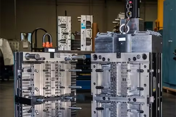
Tool Building
Fast Prototyping
Molding Manufacturing
Mold Design and Engineering
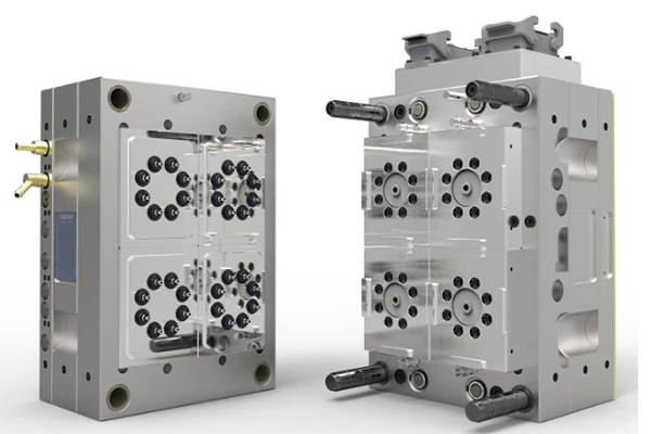
With 18 years of experience in the mold industry, we deeply understand customers‘ needs and complete mold design and tool building for you. As the most important injection tool for injection moulding products processing, the quality of injection molds is directly related to the quality of the products. Moreover, because plastic mold costs a large proportion of the production, its service life directly affects the price of injection moulded products.
Injection mold design engineering drives the development and production process of your project. With extensive industry knowledge, our engineering team has extensive experience in tool design and construction, material evaluation, quality and automation. Our mould support team is very professional in the fields of new mould development, mould modification and mould maintenance. We are committed to helping you and your projects succeed, focusing on speed, quality and cost.


Details of Our Mold Design Services
1.Get your product drawings
We get original drawings or samples from customers.
- Have prepared 3D graphics files in STL、STP、STEP、IGS、X_T、SLDPRT、PRT. This helps us quickly participate in your design.
- Have samples for reference. It doesn’t matter if there is no prepared drawing file, we can scan the sample to get the approximate appearance data and drawing file. After the product engineer has perfected it, we then make a fast prototype to verify the accuracy of the drawing file.
2.Analyze your product drawings
- The appearance and shape of the product.
- Product dimensions, tolerances and design benchmarks.
- Technical requirements (technical conditions) of the product.
- The type, shrinkage and color of the plastic used in the product.
- The surface requirements of the product (texture, polishing, oil spray, etc.).
3.Design for Manufacturability (DFM)
Our injection mold engineering software systems include: SolidWorks, PROE, UG, AutoCAD, CorelDRAW.
4.Selection of mold steel
The selection of materials for mould forming parts (cavity, core) is mainly determined according to the batch size of the product and the type of plastic. For high-gloss or transparent products, 4Cr13 and other types of martensitic corrosion-resistant stainless steel or age-hardening steel are mainly used.
For plastic products with glass fibre reinforcement, Cr12MoV and other types of hardened steel with high wear resistance should be used.
When the material of the product is PVC, POM or contains flame-retardant, corrosion-resistant stainless steel must be selected.
5.Determine cavity amount
The number of mold cavities is mainly determined based on the following 8 factors:
- 1.Production batch of products (monthly batch or annual batch).
- 2. Whether the product has side core pulling and its treatment method.
- 3. The size of the mold and the distance between the tie rods of the injection molding machine.
- 4. Product weight and injection volume of injection machine.
- 5. Clamping force.
- 6. Product accuracy.
- 7. Product color.
- 8. Economic benefits (production value of each set of molds).
After the number of cavities is determined, the arrangement of the cavities and the layout of the positions of the cavities are carried out.
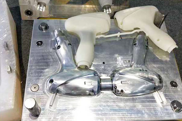
6.Determine parting surface and parting line
Generally speaking, the parting surface on the plane is easier to handle, and sometimes you should pay special attention to the parting surface of the three-dimensional form.
The selection of the parting surface should follow the following 6 principles:
- 1. It does not affect the appearance of the product, especially for products that have clear requirements on the appearance, and more attention should be paid to the effect of the parting on the appearance.
- 2. It helps to ensure the accuracy of the product.
- 3. It is conducive to mold processing, especially cavity processing. First recovery agency.
- 4. It is beneficial to the design of the gating system, exhaust system and cooling system.
- 5. Facilitate the demoulding of the product and ensure that the product is left on the side of the movable mold when the mold is opened.
- 6. Convenient for metal inserts.
7.Determine mold base
When designing the mold base, choose the standard mold base as much as possible, and determine the form, specification and thickness of the A and B board of the standard mold base.
It should be emphasized that when designing molds, standard mold bases and standard parts should be used as much as possible, because a large part of standard parts has been commercialized and can be bought on the market at any time, which will shorten the manufacturing cycle and reduce manufacturing costs.
After the size of the mold base is determined, the necessary strength and rigidity calculations should be performed on the relevant parts of the mold to check whether the selected mold base is appropriate, especially for large molds. This is particularly important.
8.Design the gating system
The design of the gating system includes the selection of the main runner and the determination of the sectional shape of the secondary runner and the size of the runner.
When designing a gating system, the first step is to choose the location of the gate. The proper choice of gate location will directly affect the quality of product molding and whether the injection process can proceed smoothly.
The selection of gate location should follow the following 7 principles:
- 1. The gate position should be selected as far as possible on the parting surface to facilitate mold processing and cleaning of the gate.
- 2. The distance between the gate position and the various parts of the cavity should be as consistent as possible, and the process should be the shortest (generally it is difficult to achieve for a large nozzle).
- 3. The gate position should ensure that when the plastic is injected into the cavity, it faces the spacious and thick-walled part of the cavity to facilitate the inflow of the plastic.
- 4. Avoid that the plastic directly rushes to the cavity wall, core or insert when it flows into the cavity so that the plastic can flow into all parts of the cavity as soon as possible, and avoid deformation of the core or insert.
- 5. Try to avoid the production of weld marks on the product. If it is necessary, make the melting marks appear in the unimportant part of the product.
- 6. The location of the gate and its plastic injection direction should enable the plastic to flow evenly along the parallel direction of the cavity when it is injected into the cavity, and facilitate the discharge of gas in the cavity.
- 7. The gate should be designed at the easiest part of the product to be removed, and at the same time, it should not affect the appearance of the product as much as possible.
9.Tooling ejection system
The ejection forms of products can be summarized into three categories: mechanical ejection, hydraulic ejection, and pneumatic ejection.
Mechanical ejection is the last link in the injection molding process. The quality of ejection will ultimately determine the quality of the product. Therefore, product ejection cannot be ignored.
The following 5 principles should be observed when designing the ejector system:
- 1. In order to prevent the product from deforming due to ejection, the thrust point should be as close as possible to the core or the part that is difficult to demold. The arrangement of thrust points should be as balanced as possible.
- 2. The thrust point should act on the part where the product can bear the greatest force, and the part with good rigidity, such as ribs, flanges, and wall edges of shell-type products.
- 3. Try to avoid the thrust point acting on the thinner surface of the product, to prevent the product from topping white, top height, etc., such as shell products and cylindrical products are mostly ejected by push plates.
- 4. Try to avoid ejecting traces from affecting the appearance of the product, and the ejecting device should be located on the hidden or non-decorative surface of the product. For transparent products, special attention should be paid to the selection of positioning and ejection form.
- 5. In order to make the product evenly stressed during ejection and avoid the deformation of the product due to vacuum adsorption, composite ejection or special forms of ejection systems are often used, such as push rod, push plate or push rod, and push tube composite Ejector, or use air intake push rod, push block and other setting devices, if necessary, an air inlet valve should be installed.
10.Cooling system
The design of the cooling system is a relatively complicated task, and the cooling effect, the uniformity of cooling and the influence of the cooling system on the overall structure of the mold must be considered.
The design of the cooling system includes the following 6 points:
- 1. The arrangement of the cooling system and the specific form of the cooling system.
- 2. Determination of the specific location and size of the cooling system.
- 3. Cooling of key parts such as moving model cores or inserts.
- 4. Cooling of side sliding block and side sliding core.
- 5. The design of cooling elements and the selection of standard cooling elements.
- 6. Design of sealing structure.
11.Design guide components
The guiding device on the plastic injection mold has been determined when the standard mold base is used. However, when precision guiding devices are required to be set according to the requirements of the product, the designer must carry out a specific design based on the mold structure.
Generally, due to the limitation of processing accuracy or the use of a period of time, the matching accuracy of the general guide device will be reduced, which will directly affect the accuracy of the product. Therefore, for products with higher accuracy requirements, precision positioning components must be designed separately.
12.Exhaust system
The exhaust system plays a vital role in ensuring the quality of product molding. There are 3 ways to exhaust:
- 1. Use the exhaust slot. The exhaust groove is generally located at the last part of the cavity to be filled. The depth of the venting groove varies with different plastics and is basically determined by the maximum clearance allowed when the plastic does not produce flash.
- 2. Use the matching clearance of cores, inserts, push rods, etc. or special exhaust plugs for exhaust.
- 3. Sometimes in order to prevent vacuum deformation of the product, it is necessary to design a vent insert.
13.Draw assembly drawing in assembly drawing
14.Convert 3D drawings to 2D drawings
15.Proofread and countersign design drawings to complete mold design
After the injection moulding tool design drawing is completed, it must be immediately submitted to the customer for approval. Only after the customer agrees, the mold can be prepared and put into production. When the customer has a big opinion that needs to make major changes, it must be redesigned and then handed over to the customer for approval until the customer is satisfied.
Get a free quote and design analysis today.
We’ll reply to you within 6 working hours.
We respect your privacy.
+86 139 2927 4777 (WhatsApp, Wechat)
Related Injection Mold Design Resources
Stack Molds: Efficiency and Precision in Injection Molding
[pac_divi_table_of_contents...
Injection Molds 101: Cold Runner VS. Hot Runner Molds
[pac_divi_table_of_contents...
Rapid Injection Mold: Solutions For Injection-Molded Parts
[pac_divi_table_of_contents...