CNC Design Guides:
Navigating the CNC Machining Process with Precision

Significance of CNC Design in Modern Manufacturing
CNC design plays a pivotal role in modern manufacturing for several compelling reasons.
Firstly, CNC design enables unparalleled precision and accuracy in the production of complex parts and components. This precision leads to higher product quality, reduced defects, and enhanced overall performance.
Secondly, CNC design offers remarkable versatility. Manufacturers can quickly reprogram CNC machines to produce different parts, making them ideal for small-batch or high-volume machining. This flexibility increases efficiency and reduces downtime during transitions between product lines.
Furthermore, CNC design reduces human error, as it relies on pre-programmed instructions, reducing the risk of mistakes associated with manual machining. This results in consistent and reliable manufacturing processes.
Additionally, CNC design supports automation, which is crucial for cost-effectiveness and competitiveness in today’s manufacturing landscape. It reduces labor costs and allows for continuous production, even in lights-out manufacturing environments.
The Connection Between CAD and CNC Machining
Computer-Aided Design (CAD) and Computer Numerical Control (CNC) machining are intricately connected processes that play a fundamental role in modern manufacturing. It ensures the seamless transition from design concepts to physical products, offering precision, flexibility, and efficiency, ultimately leading to improved product quality and cost-effectiveness. Here’s an overview of their connection:
Design to Digital Representation:
CAD software is used to create detailed digital representations of parts, products, or components. Designers use CAD tools to create 2D and 3D models, defining the geometry, dimensions, tolerances, and other specifications of the object to be manufactured.
CAD-CAM Integration:
CAD designs are seamlessly integrated with Computer-Aided Manufacturing (CAM) software. CAM software takes the CAD model and generates the toolpaths and instructions necessary for CNC machines to manufacture the physical object. This process involves specifying cutting paths, tool selection, feed rates, and other machining parameters.
Precision and Accuracy:
The CAD-to-CNC connection ensures that the design specifications are accurately translated into machine instructions. CNC machines, guided by these instructions, can achieve a level of precision and consistency that is difficult to attain through manual machining processes.
Prototyping and Iteration:
CAD allows for rapid prototyping and design iteration. When changes are needed in the design, CAD models can be easily modified and then CAM software can generate updated toolpaths, enabling CNC machines to produce the revised part.
Customization and Flexibility:
The CAD-CNC connection supports the efficient production of customized or low-volume parts. CAD designs can be quickly adapted for various applications, and CNC machines can switch between different jobs with minimal reconfiguration.
Efficiency and Cost Savings:
The integration of CAD and CNC machining streamlines the entire manufacturing process, reducing lead times and material waste. CNC machines can operate continuously, reducing labor costs and increasing productivity.
CNC Design Guides CNC Machining Process
CNC design guides the CNC machining process for various operations, including hole processing, thread processing, surface processing, angle processing, text and lettering. In all these machining processes, CNC design is crucial for accurate and efficient production. It provides the necessary information to CAM software, which, in turn, guides the CNC machine to execute the operations with precision, consistency, and adherence to design specifications. Proper CNC design minimizes errors, reduces scrap, and ensures the manufactured components meet quality standards.Here’s a brief overview of how CNC design influences each of these machining processes:
Hole Processing:
-
- Dimensional Accuracy: CNC machining is capable of achieving exceptional dimensional accuracy in hole processing, often within micrometer tolerances. This precision is crucial in industries like aerospace and automotive, where precise alignment and fits are paramount.
- Surface Effect: The surface finish inside drilled holes is typically smooth and precise. However, occasional burrs, tool marks, or surface irregularities can occur, necessitating post-processing steps like deburring or honing.
- Analysis of Difficulties: Challenges often revolve around maintaining the desired hole depth, evacuating chips effectively, and ensuring the straightness of long, narrow bores. Achieving optimal surface finish may require careful tool selection and machining strategies.
Thread Processing:
-
- Dimensional Accuracy: CNC machining excels in achieving precise thread dimensions, crucial for threaded components’ functionality and compatibility.
- Surface Effect: Threads produced through CNC machining exhibit clean, well-defined profiles. However, issues like galling, misalignment, or surface irregularities can impact the overall surface quality.
- Analysis of Difficulties: Challenges include ensuring proper thread engagement, achieving pitch accuracy, and selecting the correct tooling. Threading operations often require careful consideration of tool wear and chip control.
Surface Processing:
-
- Dimensional Accuracy: CNC machining allows for precise control of surface dimensions, vital for components with specific fits or clearances.
- Surface Effect: Surface finishes can vary widely, from mirror-like smoothness to textured or rough, depending on tooling and machining strategies.
- Analysis of Difficulties: Challenges encompass achieving the desired surface roughness, preventing tool wear, and addressing workpiece material properties. Selection of appropriate toolpath strategies and tool materials is essential for optimizing surface effects.
Angle Processing:
-
- Dimensional Accuracy: CNC machining ensures accurate angles and complex geometries, essential for components with intricate features.
- Surface Effect: Angle-machined surfaces typically exhibit well-defined and precise geometries. However, careful toolpath planning is necessary to avoid tool marks or surface imperfections.
- Analysis of Difficulties: Challenges include maintaining angular tolerances, tool selection for complex geometries, and minimizing toolpath deviations. Achieving precise angles often requires meticulous setup and machining techniques.
Text and Lettering:
-
- Dimensional Accuracy: CNC machining delivers high accuracy in reproducing fine text and lettering, crucial for labeling and branding on components.
- Surface Effect: The surface effect in text and lettering machining depends on toolpath and tool selection, resulting in either sharp, clean edges or subtle tooling marks.
- Analysis of Difficulties: Challenges involve optimizing toolpaths for intricate fonts, minimizing tool deflection, and ensuring legibility at reduced scales. Achieving the desired surface effect while maintaining dimensional accuracy requires careful planning and execution.
Material Selection for CNC Design
Material selection in CNC design is a critical decision influencing component performance and manufacturing efficiency. Engineers consider factors like mechanical properties (strength, hardness, ductility), dimensional stability, machinability, and cost.Materials range from metals to plastics and composites. For instance, Aluminum, Steel, ABS, Nylon, PMMA, Rubber and so on. Each material’s unique characteristics impact precision, durability, and suitability for specific applications. The right material selection enhances CNC machining efficiency and delivers precise, reliable, and cost-effective components for various industries and applications.
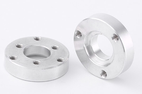
Aluminum
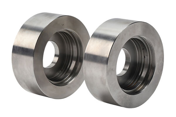
steel
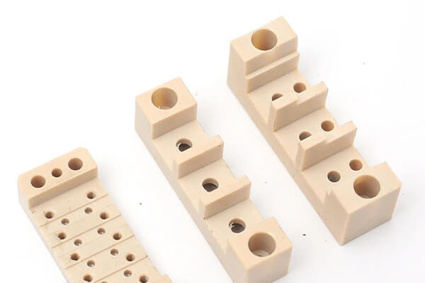
plastic
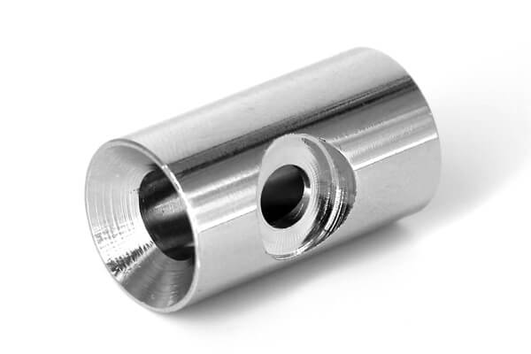
stainless steel
CNC Machine Setups and Parts Orientation
CNC machine setups and parts orientation are critical aspects of CNC (Computer Numerical Control) machining that influence the quality, efficiency, and accuracy of the manufacturing process. Here are key considerations for CNC machine setups and parts orientation:
-
- Workholding Devices: Select appropriate workholding devices such as vises, clamps, chucks, fixtures, or vacuum systems based on the size, shape, and material of the workpiece. Proper workholding ensures the workpiece remains securely in place during machining.
- Fixture Design: Design fixtures that securely hold the workpiece and allow for easy loading and unloading. Fixtures should also provide access for cutting tools and ensure that the part is properly oriented and aligned.
- Part Orientation: Align the workpiece correctly within the machine’s coordinate system. Ensure that the part’s key features, such as holes, edges, or reference surfaces, are parallel or perpendicular to the machine’s axes to minimize setups and tool changes.
- Datum Selection: Define a reference point or datum on the workpiece that serves as a starting point for CNC programming. This datum helps establish the part’s coordinate system and ensures accurate machining.
- Tool Selection: Choose appropriate cutting tools based on the material, geometry, and machining operations required. Consider factors like tool diameter, tool length, and tool geometry.
- Toolholder and Toolpath Optimization: Ensure that the toolholder and toolpath allow for proper tool reach and clearance throughout the machining process. Verify that the toolpath avoids collisions with fixtures or clamps.
- Tool Change Strategy: Plan the tool change sequence to minimize downtime. Tool change locations should be easily accessible and should not interfere with other machine components.
- Cutting Parameters: Determine the optimal cutting parameters, including spindle speed, feed rate, and depth of cut, to achieve the desired surface finish, tool life, and production speed.
- Coolant and Lubrication: Select the appropriate coolant or lubrication method to control heat generation, reduce tool wear, and improve chip evacuation during machining.
- Inspection and Quality Control: Implement a quality control process to verify part dimensions and tolerances during and after machining. Use measuring instruments such as micrometers, calipers, or CMMs (Coordinate Measuring Machines).
Effective CNC machine setups and proper parts orientation are essential for achieving precision, consistency, and efficiency in CNC machining. By carefully considering these factors, manufacturers can optimize their processes and produce high-quality components while minimizing errors and production delays.
CNC Design Software
CNC design software is essential for creating the digital models and instructions necessary to control CNC machines. The choice of CNC design software depends on the specific needs of the project, budget, and familiarity with the software. These software tools enable engineers and designers to design, simulate, and generate the CNC code required for machining operations. Here are some commonly used CNC design software packages:
-
- AutoCAD: AutoCAD is a widely used 2D and 3D CAD (Computer-Aided Design) software by Autodesk. It allows users to create detailed drawings and models for CNC machining and generates DWG files that can be used for CNC programming.
- SolidWorks: SolidWorks is a 3D CAD software known for its parametric modeling capabilities. It is often used for designing complex mechanical parts and assemblies, and it provides tools for generating CNC toolpaths.
- Fusion 360: Autodesk Fusion 360 is a cloud-based 3D CAD, CAM (Computer-Aided Manufacturing), and CAE (Computer-Aided Engineering) software platform. It allows for integrated design and CAM, making it suitable for designing and simulating parts for CNC machining.
- CATIA: CATIA (Computer-Aided Three-dimensional Interactive Application) is a high-end 3D CAD software widely used in aerospace, automotive, and other industries. It provides advanced surface modeling and CNC machining capabilities.
- NX (formerly Unigraphics): Siemens NX is a comprehensive CAD/CAM/CAE software package used for product design, engineering analysis, and CNC programming. It offers advanced machining capabilities and simulation tools.
- Mastercam: Mastercam is a dedicated CAM software that focuses on generating toolpaths for CNC machining. It supports 2D and 3D machining operations, including milling, turning, and wire EDM.
- Rhino: Rhino is a versatile 3D modeling software used in industries like jewelry design, architecture, and industrial design. While not dedicated to CNC, it can export models in formats compatible with CAM software.
- Alibre Design: Alibre Design is a 3D parametric CAD software known for its ease of use and affordability. It includes basic CAM functionality for generating toolpaths.
- SOLIDWORKS CAM: SOLIDWORKS offers an integrated CAM module that allows users to generate CNC toolpaths directly within the CAD environment, streamlining the design-to-manufacturing process.
- HSMWorks: HSMWorks is a CAM software integrated with CAD software like Autodesk Inventor and SolidWorks. It focuses on generating high-quality toolpaths for CNC machining.
- GibbsCAM: GibbsCAM is a CAM software known for its ease of use and wide range of machining strategies, making it suitable for both beginners and experienced CNC programmers.
Uploading a Technical Drawing for Quotation
If you have a part that requires CNC machining, simply send us your designs. The drawings should have these informations:
-
- The quote details of material, and surface finishes.
- Technical drawings serve as the primary reference for thread specifications, tolerance details, surface finish requirements, part marking preferences, and heat treatment specifications.
- The CAD file remains the primary reference for part design, geometry, dimensions, and feature locations.
Get a free quote and design analysis today.
We’ll reply to you within 6 working hours.
We respect your privacy.
+86 139 2927 4777 (WhatsApp, Wechat)