Custom Enclosure Design Overview
While a hardware product’s strength derives from its inside parts, it is more common to identify a product by its enclosure, the outer casing that protects and attractively designs electrical equipment.
Using the design of an IoT plant monitor product as an example, we are going to walk you through the stages for creating a custom enclosure in this post.
The concept was inspired by this amazing project, which was able to continuously monitor the moisture and temperature of plant at home with just a few sensors, a WiFi-enabled Photon developer board from Particle, and an online cloud platform.
We won’t bother about the custom enclosure appearance for the purposes of this example; instead, we’ll only concentrate on its functioning.

Step 1: Establish Product Requirements
When embarking on any design endeavor, I find it essential to commence by defining the product requirements. This initial step aids in keeping the development focused, preventing unnecessary cost and complexity. At this stage, it’s crucial to ponder the fundamental functions and purposes of the custom enclosure.
Consider the following requirements for our plant monitor enclosure:
- The custom enclosure must accommodate a Photon board, a temperature sensor, and a soil moisture sensor.
- The soil moisture sensor should penetrate at least one inch into the soil.
- The custom enclosure must facilitate interaction with two buttons located on the board’s top.
- The onboard LED must be visible through the custom enclosure.
These requirements are fundamental for a successful design. Notably, the initial requirements should not delve into highly specific design decisions, such as wall thickness dimensions. At this early stage, it’s advisable to keep the requirements as concise as possible to allow flexibility in the design process.
Pro Tip: Enclosing electronic components can elevate the system’s temperature. Consider the incorporation of a fan or an appropriate heat dissipation method if your components are prone to overheating.
Step 2: Model the Internal Components
Moving on to the custom enclosure, it is advantageous to begin by contemplating how the internal components will be positioned and held. Ideally, having a clear understanding of the components to be housed within the custom enclosure is crucial for precise design.
In our case, we have a Photon Particle board, a temperature sensor, and a soil moisture sensor. Crafting 3D models of the larger components, like the Photon board and soil moisture sensor, simplifies the 3D design process and ensures relevance. You can often obtain dimensional drawings from the manufacturer, or in some cases, the actual 3D models.
I was able to access dimensions for both the Photon board and the soil moisture sensor, enabling me to create simplified 3D representations. These placeholder models need not replicate every feature of the components; they should primarily convey the outer dimensions and mating features.
Step 3: Develop the Custom Enclosure Shell
With models of the electronic components in hand, it’s time to design the custom enclosure around them. I initiate this phase by creating a shell, essentially forming an open box structure.
While introducing features, it’s important to maintain uniform wall thicknesses. For mass manufacturing, such as injection molding, uniform wall thicknesses are essential. I’ve opted for a .040” wall thickness, suitable for both 3D printing and injection molding.
Step 4: Integrate Slot and External Holes for Soil Moisture Sensor
One of our stipulated requirements mandates the insertion of the soil moisture sensor at least one inch into the soil. While one option is to route wires from the board to the sensor outside the custom enclosure, I prefer a fully packaged product.
To achieve this, I’m adding a slot that will securely hold the moisture sensor in a vertical position, enabling the probes to extend through the enclosure’s bottom.
Step 5: Create Cutouts for Wire Connections and Micro-USB Connector
To accommodate the wires that need to be soldered on top of the moisture sensor, we should make cutouts while preserving the slot’s integrity. Additionally, I’ll introduce a cutout for the micro-USB connector, allowing the board to align with the connector inside this slot.
Step 6: Introduce Support Ribs for the Photon Board
The Photon board is presently supported on one side by its micro-USB connector, but it’s prudent to include additional supports where the board can rest. Fortunately, there are no components mounted on the underside of the Photon board, eliminating concerns about potential interference. A straightforward approach is to create uniform-thickness ribs on which the board can securely sit.
Step 7: Incorporate Features for Lid Fastening
Now it’s time to address how the lid will be fastened in place. I prefer using socket head cap screws, so let’s introduce features along the enclosure’s perimeter to accommodate a fastener passage. These features adhere to standard injection molding practices, with bosses encircling the fastener holes and additional ribs for structural reinforcement. Consistency is maintained with a uniform thickness of .040”.
Step 8: Add Features for Nuts
A practical technique for utilizing metal fasteners in plastic components is to countersink the nut precisely on the underside of the part, preventing it from rotating while fastening.
Step 9: Apply Fillets to Outer Corners
In this step, we’ll round the external corners, reducing stress concentration and enhancing the enclosure’s aesthetic appeal. While maintaining uniform thickness, the outer radius (0.140”) will be slightly larger than the inner radius (0.100”). Additionally, we’ll fillet the internal corners conservatively to avoid adding excess material and increasing wall thickness.
Step 10: Lid Design
Transitioning to the lid, we’ll employ similar features, including creating a shell, adding bosses for fastener passages, countersinking the fasteners into the top, and applying fillets to the outer corners for continuity with the enclosure’s bottom.
The design of the bosses for fasteners is based on the uniform wall thickness principle. These bosses facilitate countersinking from the other side, and they are intentionally kept slightly shorter than the outer wall height to prevent interferences.
Step 11: Apply Fillets to Corners and the Top Edge
Similar to Step 9, we will round the outer corners of the lid to reduce stress concentration and ensure alignment with the bottom of custom enclosure.
Step 12: Introduce a Protrusion to Secure the Top of the Micro-USB Connector
A small boss will be added to secure the top of the micro-USB connector, ensuring it remains in place within the slot at the base of custom enclosure.
Step 13: Create Openings for Buttons and LED Light
To meet our requirements, openings will be generated to enable interaction with the buttons on the board and to allow visibility of the LED light.
Step 14: Implement a Rib for Securing the Moisture Sensor
Considering that the moisture sensor may contact the lid when inserted into the soil, a rib will be added to anchor the sensor securely in a more suitable position.
Step 15: Round Internal Corners
In the final step, we’ll apply small-radius fillets to all the sharp internal corners. This not only enhances aesthetics but also mitigates stress concentrations. Careful consideration is given to wire routing, ensuring there is ample space (approximately half an inch) above the board for wires and the small temperature sensor. This foresight accommodates easy assembly and wire management.
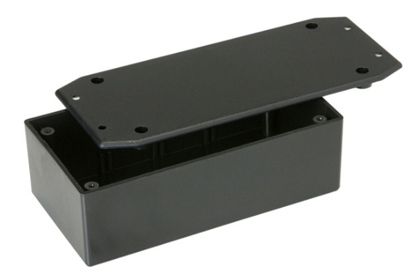
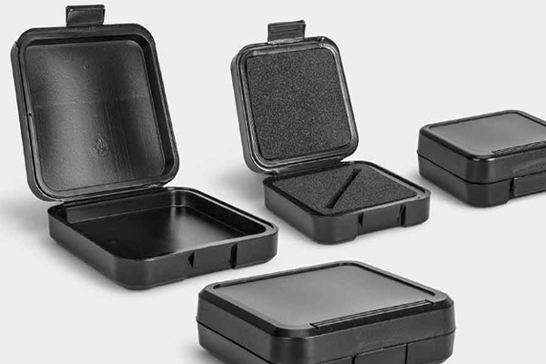
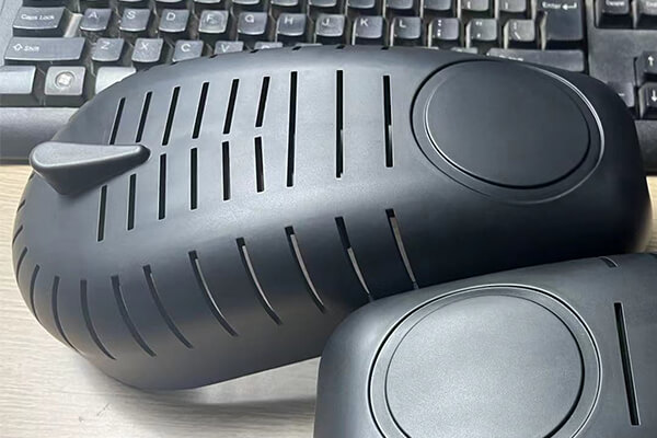
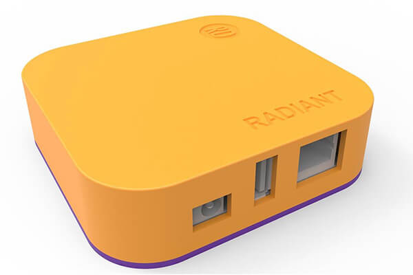
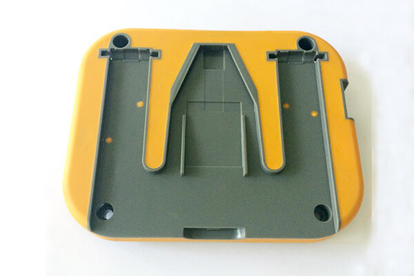
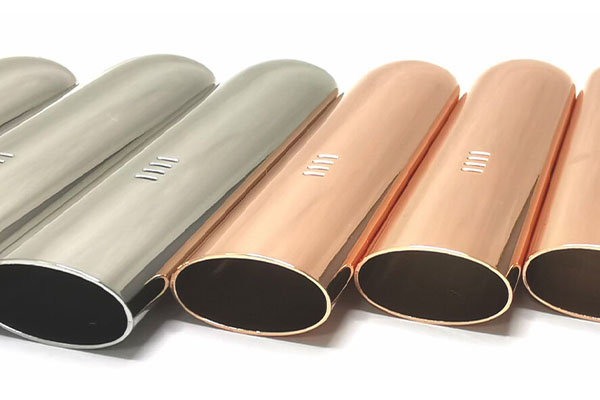
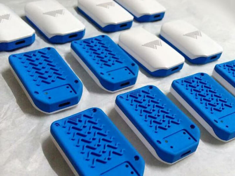
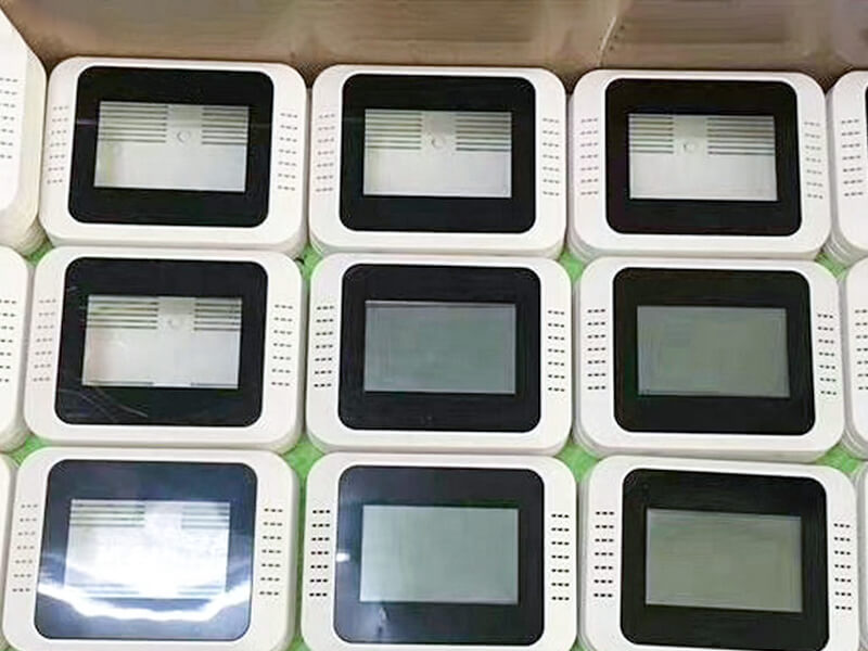
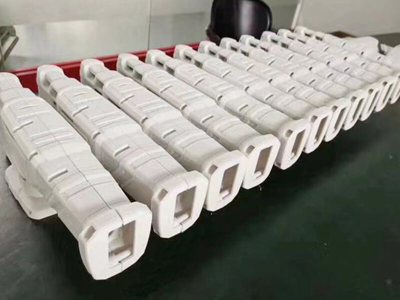
Examples of Plastic Covers Made in Sungplastic
At Sungplastic, we have extensive experience in manufacturing custom plastic shells.
We hope that these tips will be useful to you as you design and prototype your own product enclosure. Contact us immediately to begin 3D printing your custom enclosure design!
Consult with us for further information on custom enclosure design aspects, including how to create snap-fit components, select the best fasteners for 3D printed parts, and do a tolerance analysis, CNC machining service, injection molding service and so on.
Sungplastic provides the best services for you!
Get a free quote and design analysis today.
We’ll reply to you within 6 working hours.
We respect your privacy.
+86 139 2927 4777 (WhatsApp, Wechat)