Injection Mold Acceptance Criteria
Injection mold acceptance criteria are the standards and specifications that must be met before an injection mold can be considered acceptable for injection molding. This may include visual inspections, measurements and functional tests. It is important to note that acceptance criteria may vary depending on the specific molded product, materials used and customer requirements. These acceptance criteria are usually established by the plastic products manufacturer or customer. And they may include the following seven items:
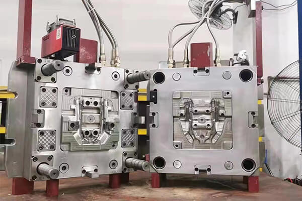
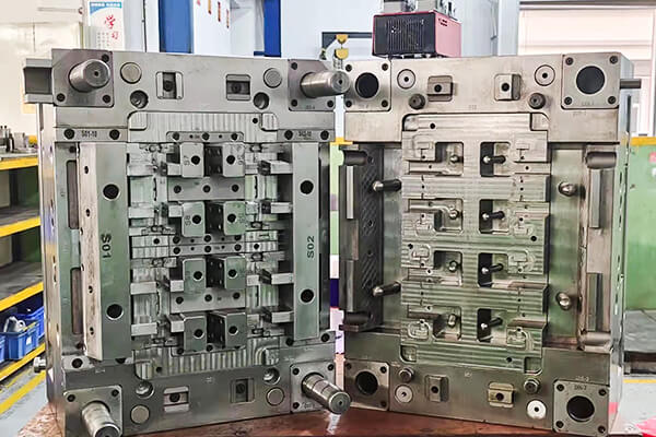
Injection mold appearance
1. Whether to print the plastic mold number, plastic Injection mold weight (KG), and mold dimensions (mm) on the nameplate, the characters are all printed in 1/8-inch characters, and the characters are clear and neatly arranged.
2. Whether the nameplate is fixed on the mold leg close to the rear formwork and the reference angle (15mm away from both sides), fixed with four rivets, which is reliable and not easy to peel off.
3. Whether the cooling water nozzle is inserted with a plastic block, ¢10 tube, and the specifications can be G1/8″, G1/4″, G3/8″. If there are special requirements in the contract, follow the contract.
4. Whether the cooling water nozzle protrudes from the surface of the mold base, and the head of the water nozzle is recessed from the outer surface by no more than 3mm.
5. Whether the diameter of the air-avoiding hole of the cooling water nozzle is ¢25, ¢30, ¢35mm, and whether the outer edge of the hole is chamfered, and the chamfer is larger than 1.5×45, and the chamfer is consistent.
6. Whether there is an in and out mark on the cooling water nozzle, the water inlet is IN, and the water outlet is OUT, and sequence numbers are added after IN and OUT, such as IN1 and OUT1.
7. Mark whether the English characters and numbers are capitalized (5/6″), the position is 10mm directly below the faucet, and the writing is clear, beautiful, neat, and evenly spaced.
8. Whether the inlet and outlet oil nozzles and air inlet and outlet nozzles are the same as the cooling water nozzles, and add G (air) and O (oil) before IN and OUT.
9. On the upper and lower sides of the mold installation direction, there are water nozzles, whether it is built-in, and whether there is a diversion groove or a support column below to protect it.
10. Whether there is a support column under the built-in grease nozzle or water nozzle to protect it.
11. Whether there is a reference angle symbol for each template on the formwork, capitalized English DATUM, the character height is 5/16″, and the position is 10mm from the edge. The writing is clear, beautiful, neat and evenly spaced.
12. Whether there is a part number for each template, the number is 10mm from the bottom directly below the reference angle symbol, and the requirements are the same as No. 11.
13. The installation of mold accessories, such as leaking oil cylinders, faucets, and pre-reset mechanisms, may impact mold hoisting and storage. Therefore, supporting legs should be used to protect them during installation.
14. The method for fixing the support legs during installation should be considered. The support legs can either be attached to the formwork with screws passing through them or fastened to the formwork with machined external threads.
15. The ejection hole of the plastic mold should meet the specifications of the injection molding machine. For larger molds with a length or width greater than 500mm, only one center cannot be used for ejection. In addition, the diameter of the ejection hole should be 5-10mm larger than the ejector rod, with the exception of small molds.
16. The positioning ring should be securely fixed, generally with three M6 or M8 inner hexagonal screws. The diameter of the positioning ring is typically ¢100 or ¢150mm, and it should be positioned 10mm higher than the top plate. If there are special requirements in the contract, the same shall apply.
17. The mounting hole of the positioning ring must be a counterbore, and it is not allowed to be directly attached to the top surface of the formwork.
18. When the plastic Injection mold weighing more than 8000KG is installed on the injection molding machine, whether to press the screw by perforation, or not to press the plate alone. If the equipment adopts a hydraulic locking mold, screw holes must also be added to prevent the failure of the hydraulic mechanism.
19. Whether the ball R of the sprue sleeve is larger than the ball R of the nozzle of the injection molding machine.
20. Whether the diameter of the sprue sleeve inlet is larger than the diameter of the nozzle injection port.
21. Whether the overall dimensions of the mold conform to the specified injection molding machine.
22. Whether the mold with direction requirements is installed or not, the installation direction is marked with an arrow on the front template or the rear mold. There should be “UP” next to the arrow. Both the arrow and the text are sprayed with yellow paint with a leak board, and the height of the character is 50mm.
23. Whether there are pits and rust on the surface of the formwork, redundant and unused suspension rings, water, air, oil holes, etc., and other defects that affect the appearance.
24. Whether each plate of the formwork has a chamfer greater than 1.5mm.
25. Whether the mold is easy to hoist and transport, and the mold parts must not be disassembled during hoisting (except for the oil cylinder, which needs to be packaged separately). The lifting ring interferes with the faucet, oil cylinder, pre-reset lever, etc., and the position of the lifting ring hole can be changed.
26. Whether each mold part weighing more than 10KG has a suitable ring hole, if not, corresponding measures must also be taken to ensure that the parts are easy to disassemble and install. The size of the lifting ring and the position of the ring hole are designed according to the relevant enterprise standards.
27. Whether the lifting ring can be screwed to the bottom, and the lifting is balanced.
28. If the ejector mechanism such as the ejector rod and the ejector block interfere with the slider, etc., whether there is a forced pre-reset mechanism, and whether the ejector plate has a reset travel switch.
29. Whether there is a travel switch to control the core pulling and ejection of the oil cylinder, and the installation is reliable.
30. Whether the mold oil separator is fixed and reliable.
31. Whether the oil pipe connecting the oil separator and the oil cylinder is a rubber hose, and the joint is a standard piece.
32. Whether there are garbage nails on the thimble plate.
33. Whether the area of the mold support head is 25%-30% of the area of the formwork behind the square legs.
34. Whether the support head is 0.05-0.15mm higher than the mold leg, and does not interfere with the ejection hole.
35. Whether the clamping device is installed reliably, with positioning pins, installed symmetrically, no less than 4 (2 for small molds).
36. Whether there is a spring between the front template and the nozzle plate of the three-plate mold to assist the mold opening.
37. After all the spare parts of the large mold are installed, is there any interference in the mold clamping?
38. If the injection molding machine uses an extended nozzle, is there enough space inside the positioning ring to ensure that the extended nozzle of the standard injection molding machine with a heating ring can be inserted?
39. Are all jacks removable from a hole through the base plate and ejector base at an angle consistent with the angle of the jacks?
40. Whether the bottom surface of the screw mounting hole is flat.
41. Whether the screws above M12 (including M12) are imported screws (grade 12.9).
The status of ejection reset, ferrule extraction, and pick-up the parts
1. Whether the ejection is smooth, free from stagnation and abnormal noise.
2. Whether the surface of the inclined top is polished, and the inclined top surface is 0.1-0.15mm lower than the core surface.
3. Whether there is a guide chute on the inclined roof, the material is tin bronze, built in the rear mold frame, fixed with screws, and positioned with positioning pins.
4. Whether the end surface of the ejector rod is 0-0.1mm lower than the core surface.
5. Whether there is an oil groove on the sliding parts (except the ejector rod), the surface is nitrided, and the hardness is HV700. (Large sliders are on customer request).
6. Whether all ejector pins have anti-rotation positioning, according to the three positioning methods of enterprise standards, and have numbers.
7. Whether the ejector plate is reset to the end.
8. Whether the ejection distance is limited by a limit block. The limit material is 45# steel, which cannot be replaced by screws, and the bottom surface must be flat.
9. Whether the return spring is a standard part, and the two ends are not polished or cut off.
10. Whether the bottom surface of the installation hole of the return spring is flat, and the diameter of the installation hole is 5mm larger than that of the spring.
11. Push out and reset, pull out the ferrule, and pick up the parts. 11 Is there a guide rod inside the spring with a diameter exceeding ¢20mm, and the guide rod is 10-15mm longer than the spring?
12. Under normal circumstances, whether to use short-section blue mold springs (light load), red for heavy loads, and yellow for light loads.
13. Whether the spring has a pre-compression amount, the pre-compression amount is 10%-15% of the total length of the spring.
14. Whether the material of the pressure plate of the inclined roof and the slider is 638, the nitriding hardness is HV700 or T8A, and the quenching treatment is HRC50-55.
15. Whether there is a travel limit for the slider and core-pulling. The small slider is limited by a spring. If the spring is inconvenient to install, a wave screw can be used. The cylinder core-pulling has a travel switch.
16. Slanted guide pillars are generally used for slider core pulling. Whether the angle of the inclined guide pillars is 2-3 degrees smaller than the angle of the locking surface of the slider. If the stroke is too large, an oil cylinder can be used.
17. If the core-pulling forming part of the oil cylinder has a thick wall, whether to add a self-locking mechanism to the oil cylinder.
18. If there are ribs, columns and other difficult-to-release structures in the inclined roof and slider core-pulling forming part, whether to add an anti-jack mechanism.
19. The large slider cannot be set above the installation direction of the mold. If it cannot be avoided, whether to increase the spring or increase the number and increase the core-pulling distance.
20. The maximum ratio of slider height to length is 1, whether the length dimension is 1.5 times the width dimension, and the height is 2/3 of the width.
21. The sliding fit length of the slider is greater than 1.5 times the length in the direction of the slider. After the slider completes the core-pulling action, whether the length remaining in the chute is less than 2/3 of the length of the chute.
22. Whether the lead-in angle of the slider in each direction (especially the left and right sides) is 3-5 degrees to facilitate research and prevent flashing. The sliding distance of the slider is 2-3mm larger than the core-pulling distance, similar to that of the inclined top.
23. Whether the large slider (weight over 30 kg) guides the T-shaped slot with a detachable pressure plate.
24. The slider is limited by a spring. If the spring is inside, whether the spring holes are all on the rear mold or the slider; if the spring is outside, whether the spring fixing screw has wires at both ends, so that the slider can be easily disassembled.
25. Whether the sliding distance of the slider is greater than the core-pulling distance by 2-3mm, and the inclined top is similar.
26. Is there a wear-resistant plate under the large slider (the width of the slider exceeds 150mm), the material of the wear-resistant plate is T8A, quenched to HRC50-55, and the wear-resistant plate is 0.05-0.1mm higher than the large surface, and the wear-resistant plate should be refuelled groove.
27. Whether there is a wear-resistant plate surface 0.1-0.5mm higher than the locking surface of the large slider (width more than 200mm), and an oil groove on it.
28. Whether the slider pressure plate is used for positioning and locking.
29. For sliders with a width of more than 250mm, whether to add one or several guide blocks in the middle part of the lower part, the material is T8A, quenched to HRC50-55.
30. If the product has a tendency to stick to the front mold, whether the side wall of the rear mold is added with a leather pattern or fire pattern, no deep undercut, no undercut ribs or pitting after manual grinding.
31. If a barb is added to the push rod, whether the direction of the barb is consistent and the barb is easy to remove from the product.
32. The size of the embryonic head of the ejector pin, including whether the diameter and thickness have been changed without authorization or gaskets.
33. Whether the matching gap between the ejector pin hole and the ejector pin, the length of the sealing section, and the smoothness of the ejector pin hole are processed according to the relevant enterprise standards.
34. Whether the ejector rod moves up and down.
35. When the plastic product is ejected, it is easy to follow the inclined top. Whether there is a groove or etching on the ejector rod does not affect the product’s appearance.
36. If there is a case where the push plate is ejected, whether the ejector pin is delayed to prevent whitening.
37. The end surface of the return rod is flat, without spot welding, and there is no gasket or spot welding at the bottom of the embryo head.
38. Whether the avoidance hole of the inclined roof on the formwork is too large to affect the appearance.
39. Whether the top block fixed on the ejector rod is reliably fixed, the non-forming part around it should be processed with a slope of 3-5 degrees, and the lower part is chamfered.
40. Whether the plastic product is easy to pick up by the robot.
41. When the three-plate mold is taken by the manipulator, whether the limit tie rods are arranged on both sides of the mold installation direction to prevent the limit tie rods from interfering with the manipulator, or to add pull plates outside the mold base.
42. Whether the nozzle plate of the three-plate mold guides and slides smoothly, and the nozzle plate is easy to pull apart.
43. For the mold whose oil circuit is processed on the formwork, whether to blow off the iron filings in the oil circuit to prevent damage to the equipment’s hydraulic system.
44. Whether the oil passage and air passage are smooth, and the hydraulic ejector is reset in place.
45. Use the manipulator to pick up the parts, whether the guide post affects the manipulator to pick up the parts.
46. Does the self-made formwork have a guide post offset by OFFSET to prevent the wrong installation.
47. Is there an air outlet at the bottom of the guide sleeve, so as to discharge the air in the closed cavity formed when the guide post enters the guide sleeve.
48. There can be no gaps in the installation of positioning pins.
Cooling system of plastic Injection mold
1. Whether the cooling water channel is sufficient and smooth, and meets the requirements of the drawing.
2. Whether the seal is reliable, has no water leakage, is easy to repair, and the faucet is wrapped with raw material tape when installing.
3. Whether to conduct a water test before the mold test, the water inlet pressure is 4Mpa, and the water is passed for 5 minutes.
4. Whether the sealing groove for placing the sealing ring is processed in size and shape according to the relevant enterprise standards, and is opened on the mold base.
5. Whether apply butter when the sealing ring is placed, and it is higher than the surface of the mold base after placement.
6. Whether the waterway baffles are made of materials that are not susceptible to corrosion, generally brass sheets.
7. Whether the front and rear molds adopt centralized water transportation.
General pouring system (excluding hot runner) of plastic Injection mold
1. Whether the sprue surface in the sprue bushing is polished to ▽1.6.
2. Whether the sprue is polished to ▽3.2 or 320# oilstone.
3. Whether the partial section of the three-plate mold sprue on the back of the front formwork is trapezoidal or circular.
4. The material handle of the three-plate mold is broken on the nozzle plate, whether the diameter of the runner inlet is less than ¢3, and there is a 3mm deep step recessed into the nozzle plate at the ball head.
5. Whether the ball head pulling rod is reliably fixed, it can be pressed under the positioning ring, it can be fixed with a headless screw, or it can be pressed with a pressure plate.
6. Whether there is a distance of about 10-12mm between the top plate and the nozzle plate.
7. Whether the opening distance between the nozzle plate and the front formwork is suitable for the pick-up handle, in general, the opening distance = the length of the material handle ÷ 20-25, and it is greater than 120mm.
8. Whether the limit of the front formwork of the three-plate formwork is limited by the limit rod.
9. Whether the gate and runner are processed by machine tools (CNC, milling machine, EDM) according to the drawing size, and manual grinding machine processing is not allowed.
10. Whether the injection gate is processed according to the injection gate specification.
11. There is a small protrusion on the front mold at the injection gate, and a corresponding pit on the back mold.
12. Is there an extension at the front end of the runner as a cold slug hole?
13. Whether the Z-shaped undercut of the pulling rod is smoothly transitioned.
14. Whether the surface of the runner on the parting surface is circular, and there is no misalignment between the front and rear molds.
15. Whether there is surface shrinkage of the latent gate on the ejector pin.
16. Whether the diameter and depth of the cold slug cavity of transparent products meet the design standards.
17. Whether the material handle is easy to remove, there is no trace of a gate on the appearance of the product, and there is no residual material handle at the assembly part of the product.
18. Hook latent gate, whether the two parts of the insert are nitrided, and the hardness is HV700.
Hot runner system of Injection mold
1. Whether the wiring layout of the hot runner is reasonable, easy to overhaul, and the wiring numbers correspond to each other.
2. Whether safety testing is carried out to avoid safety accidents such as electric leakage.
3. Whether the temperature control cabinet, hot nozzle, and collector plate meet the customer’s requirements.
4. Whether the main sprue sleeve is connected to the collector plate with threads, the bottom plane is contacted and sealed, and the surrounding is welded and sealed.
5. Whether the current collecting plate is in good contact with the heating plate or heating rod, the heating plate is fixed with screws or studs, the surface fits well without flashing cracks, and the fitting gap between the heating rod and the current collecting plate is not greater than 0.05-0.1mm (h7/ g6), easy to replace and maintain.
6. Whether to use a J-type thermocouple and correspond to the temperature control table.
7. Whether there is a dead corner of the stock at the plugs at both ends of the collector plate, so as to avoid the decomposition of the stock, the plug screws are tightened and welded and sealed.
8. After the collector plate is installed with the heating plate, whether the distance between the heating plate and the template is within the range of 25-40mm.
9. Whether each group of heating elements is controlled by thermocouples, and whether the thermocouples are arranged in a reasonable position to accurately control the temperature.
10. Whether the nozzle of the hot runner is in close contact with the heating ring, the upper and lower ends are exposed, the length of the cold material section and the nozzle are processed according to the drawing, and the dimensions of the avoidance section, sealing section and positioning section at the upper and lower ends meet the design requirements.
11. Whether the size of the outlet of the nozzle is less than ¢5mm, so as to avoid shrinkage of the product surface due to the large material handle.
12. Whether the head of the nozzle is made of copper or aluminum as the sealing ring, and the height of the sealing ring is 0.5mm higher than the large surface. The diameter of the inlet of the nozzle head is larger than the size of the outlet of the collector plate, so as to avoid overflow due to the heat extension of the collector plate and the misalignment of the nozzle.
13. Due to the heat becoming longer, whether the collector plate is reliably positioned, at least two positioning pins, or fixed with screws.
14. Is there a thermal insulation pad between the collector plate and the formwork, and asbestos mesh, stainless steel, etc. can be used?
15. Is there a spacer directly below the main sprue bushing and above each thermal nozzle to ensure the sealing? The spacer is made of stainless steel with poor heat transfer or heat-insulating ceramic gaskets.
16. If the pads on the upper part of the hot nozzle protrude from the top plate, except that they should be 0.3mm higher than the top plate, whether these pads are leaked in the positioning ring of the injection molding machine.
17. Whether the error between the set temperature and the actual displayed temperature of the temperature control meter is less than ±2°C, and the temperature control is sensitive.
18. Whether the cavity is connected with the installation hole of the thermal nozzle.
19. Whether the wiring of the hot runner is bundled and covered with a pressure plate to avoid breaking the wire during assembly.
20. If there are two sockets of the same specification, are they clearly marked to avoid the wrong insertion?
21. Whether the control wire has a sheath and is not damaged, it is generally a cable.
22. Whether the structure of the temperature control cabinet is reliable and the screws are not loose.
23. The socket is installed on the bakelite board, whether it exceeds the maximum size of the template.
24. Whether the needle tip of the pinpoint thermal nozzle protrudes from the front die surface.
25. Whether the wire is leaking out of the mold.
26. Whether all the places where the current collector plate or template contacts the wires are rounded and transitioned to avoid damage to the wires.
27. Are all collector plates and nozzles made of P20 material?
28. Before the formwork is assembled, whether there is no short circuit in all lines.
29. Are all wires properly connected and insulated?
30. After the template is installed and clamped, check whether all lines are checked again with a multimeter.
Conditions of injection molding parts, parting surfaces, and exhaust grooves
1. Whether there are unevenness, pits, rust and other defects that affect the appearance of the front and rear mold surfaces.
2. When the insert is matched with the mold frame, whether the four R corners are lower than the gap of 1mm (the largest point).
3. The parting surface is kept clean and tidy, without a portable grinding wheel for grinding to avoid voids, and there is no depression in the sealing part.
4. Whether the depth of the exhaust groove is less than the overflow value of the plastic, PP is less than 0.03mm, ABS, PS, etc. are less than 0.05mm, the exhaust groove is processed by machine tools, and there is no trace of manual grinding machine.
5. Whether the research and matching of the inserts are in place (use several different inserts to develop and match to prevent the size error of the inserts), the placement is smooth and the positioning is reliable.
6. Whether the inserts, insert cores, etc. are reliably positioned and fixed, and the circular parts are locked. There is no copper or iron sheet under the insert. If it is welded, it will form a large surface contact and be ground flat.
7. The front mold is polished in place. (according to contract requirements)
8. The surface of the ribs and pillars of the front mold and back mold should be free of fire patterns and knife marks, and should be polished as much as possible. The pinhole surface of the cylinder is finely twisted with a reamer, without fire patterns and knife marks.
9. Whether the end surface of the ejector rod is consistent with the core.
10. Whether the insertion part has a slope greater than 2 degrees to avoid a puncture, and the insertion part has no thin blade structure.
11. Whether all lines, knife marks and fire patterns are removed with oilstone on the front of the rear mold of the mold, and if it is not damaged, it can be kept.
12. Whether each part of the mold has a number.
13. Whether there are no defects such as undercuts and chamfers in the molding parts of the front and rear molds.
14. Whether the deep ribs (more than 15mm) are inlaid.
15. Whether the ribs are ejected smoothly.
16. For a product with a modulus cavity, if it is a left-right symmetrical piece, whether to indicate L or R, if the customer has requirements for the position and size, it must be according to the customer’s requirements. If the customer does not require it, it should be added at a place that does not affect the appearance and assembly. above, the font size is 1/8″.
17. Whether the research and matching of the locking surface of the formwork are in place, and more than 70% of the area is touched.
18. Whether the ejector rod is arranged closer to the side wall or next to the ribs and bosses, use a larger ejector rod.
19. Whether to indicate the number 1, 2, 3, etc. for the same piece (the printing method is the same as above).
20. Whether the cavity and parting surface are wiped clean.
21. Whether the moving parts such as cylinder pins and ejector pins need to touch the front mold surface and the small inlaid pillars below ¢3mm are inserted into the front mold.
22. Whether the penetration surface, insertion surface and parting surface are researched and matched in place.
23. Whether the sealing part of the parting surface meets the design standards (10-20mm for medium-sized molds, and 30-50mm for large-scale molds, and the remaining parts are machined to avoid air).
24. Whether the skin texture and sandblasting meet the customer’s requirements.
25. The surface of the product should be etched or sandblasted, whether the dial slope is 3-5 degrees or the deeper the skin texture, the larger the slope.
26. Is the dialling slope of transparent parts larger than that of ordinary products? Generally, the dialling slope of PS is greater than 3°, and that of ABS and PC is greater than 2°.
27. Whether there are anti-shrinkage measures for the finished screw columns with appearance requirements.
28. The front mold has holes, pillars and other products that require clear corners at the root. Whether the holes and pillars are inlaid with the front mold.
29. Whether to use a cylinder needle for screw posts with a depth exceeding 20mm.
30. If the screw column has chamfers, whether the corresponding cylinder and column are chamfered.
31. Whether the wall thickness of the product is uniform (within 0.15mm).
32. Whether the width of the rib is less than 60% of the wall thickness of the appearance surface (except for customer requirements).
33. Whether there is a reliable fixing method for the inlaid core on the inclined roof and the slider (screw tight or embryo head inserted from the back).
34. The front mold is inserted into the back mold or the back mold is inserted into the front mold. Whether the bevel is locked around or machined to avoid air.
35. Whether transparent PS, AS, PC, PMMA, etc. adopt a strong detachment structure.
36. Whether the mold material, including the model and processing status, is in accordance with the contract requirements.
37. Whether to mark the special number, date code, material number, logo, trademark and other characters. (The date code is based on customer requirements, such as useless standard parts).
38. Whether the direction of the logo on the transparent part is printed correctly.
39. Whether the front and rear molds of transparent parts are polished to a mirror surface.
Packaging for injection mold
1. Whether the mold cavity is sprayed with anti-rust oil.
2. Whether the sliding parts are greased.
3. Whether the inlet of the sprue sleeve is blocked with butter.
4. Whether the mold is equipped with clamping pieces, and the specifications meet the design requirements (three-plate mold stripping plate and rear mold are fixed) at least two pieces.
5. Whether electronic documents such as mold product drawings, structural drawings, waterway drawings, spare parts and mold material supplier details, instruction manuals, packing lists, and molding conditions are complete.
6. Whether the appearance of the mold is sprayed with blue paint (if the customer has special requirements, according to the contract and technical requirements).
7. Whether the product has an assembly conclusion.
8. Whether there are surface defects and refinement problems in the product.
9. Whether the spare parts, spare parts and wearing parts are complete with details, and whether there is a supplier name.
10. Whether there is a release order from the marketing department.
11. Whether the mold is packed with film.
12. Whether to use paint to spray the name of the mold and the direction of placement in wooden boxes.
13. Whether the wooden box is fixed firmly.

About Sungplastic
Sungplastic is a plastic product manufacturer with rich experience in injection molding. According to the different product development requirements, we flexibly adjust the manufacturing process to achieve high quality, high efficiency and more economical.
We offer a variety of manufacturing services: Rapid Prototyping, Tool Making, Injection Molding, Product Design and Development, CNC Machining and Metal Stamping. You can choose from a variety of plastics, silicone rubber, or metal for your product. Regardless of mass production or small batch customization, Sungplastic has always been committed to providing assured, efficient and more economical one-stop processing services for your projects.
Contact us for a free quote and project review.
Get a free quote and design analysis today.
We’ll reply to you within 6 working hours.
We respect your privacy.
+86 139 2927 4777 (WhatsApp, Wechat)