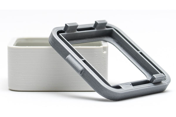
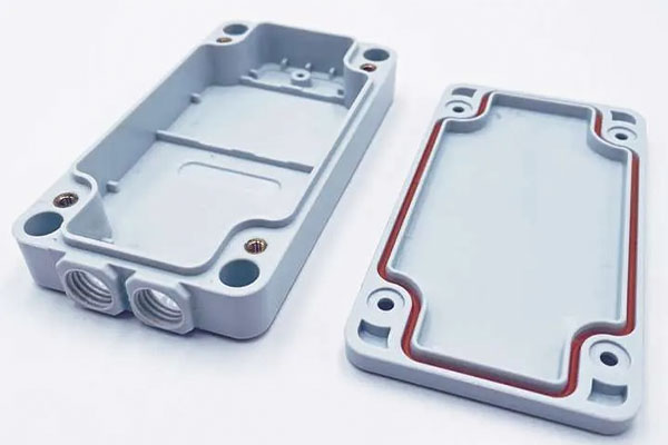
3D Printed Enclosures and Injection Molded Enclosures Design
What are 3D printed enclosures and injection molded enclosures, and How do we make and apply them?
The interior components of an electronic or mechanical goods are typically what give it its power, but their plastic shells let consumers recognize these things. The system looks good and is easy to use because to those outside shells that also shield the inside components. We’ll guide you through the process of creating prototype plastic 3D printed enclosures or injection molding enclosures in this post.
This article’s example of 3D printed enclosures design is derived from an ongoing project. The application is used to continuously check the indoor temperature and moisture content. There are sensors and a WiFi-capable Photon developer board inside the container. The appearance of the 3D printed enclosures won’t be a concern for the duration of this article. We’re concentrating on utility instead.
Next, read more about our design for 3D printed enclosures and injection molded enclosures.


Step 1: Commence with Defining Product Requirements
When embarking on the creation of customized 3D printed enclosures or molded enclosures, it is imperative to initiate the process by establishing the product’s fundamental requirements. Generating a problem tree for the mechanical 3D printed enclosures or molded enclosures design assists in comprehending the specific specifications and essential design criteria. This approach also aids in averting basic errors and the unnecessary complexity of 3D printed enclosures or molded enclosures designs. It’s essential to remember that mistakes made during this stage can escalate the manufacturing costs in the later phases.
So, how do you go about designing an electronic enclosure for plant monitoring? Let’s outline our prerequisites:
- The 3D printed enclosures or molded enclosures must accommodate a photon board, a temperature sensor, and a soil moisture sensor.
- The soil moisture sensors need to be able to penetrate the soil to a depth of at least one inch.
- The two buttons located on the top of the board should remain accessible when the enclosure is in use.
- The onboard LED must be visible even when the enclosure is fully sealed.
The features listed above delineate the system requirements, and our plastic enclosure will initially take the form of a basic geometric structure (essentially, a box) to house the internal system.
The 3D printed enclosures or molded enclosures design will evolve further as additional considerations arise. For instance, during product development, it’s important to keep an eye on weight reduction. As a general rule, commencing with a lightweight design and adding material as necessary is a prudent approach. This consideration primarily revolves around wall thickness and the overall dimensions of the enclosure.
Pro Tip: Electronic components can generate substantial heat, so it is crucial to carefully select an appropriate enclosure material and obtain comprehensive electronic component specifications to determine the cooling requirements. It’s advisable to incorporate natural or forced conventional cooling systems to prevent overheating.
Step 2: Model the Internal Components
Now that we have a clear understanding of the product requirements, the next step is to outline how the internal components will be housed and positioned within the enclosure. This necessitates a deep comprehension of the enclosure components used in the system, their functions, and their accessibility for operation. In our example, the system comprises a Photon Particle board, a temperature sensor, and a soil moisture sensor, all of which must be securely contained within the custom plastic enclosure.
By initially modeling the internal hardware of the enclosure, we can craft a custom enclosure that not only safeguards but also secures the Photon board and sensors. Additionally, it is crucial to create a design that incorporates accurately scaled and dimensioned components, ensuring that the 3D model reflects the mounting holes and the profile of the plastic enclosure with precision.
Pro Tip: Manufacturers often provide specification sheets, 2D drawings, or 3D models of electronic components, which can be extremely useful in this phase. It’s important to note that the placeholder models do not need to capture every nuance of the part; the critical dimensions, such as mating features and overall size, should be accurately represented since these will influence how the parts interact and are mounted.
For example, while the models of the soil moisture sensor and Photon board may appear rather blocky, they do accurately represent the extent of the components, as shown below.
Step 3: Crafting the Protective Shell
With the component models in hand, the next step is to commence the design of the plastic casing that will encompass them. We initiate this process by creating a basic open-box shape, typically in the form of a rectangular prism. It’s essential to maintain uniform wall thicknesses as you add features, as this aligns with best practices for one of our chosen production methods: injection molding.
In our specific case, we opt for a wall thickness of .040 inches, which suits both 3D printed prototypes and injection molding production.
Step 4: Incorporating Slots and External Openings for the Soil Moisture Sensor
Recalling our design requirements, we are reminded that the soil moisture sensor should penetrate the soil to a depth of at least one inch. While an option could be to run wires from the board to the sensor outside of the enclosure, we have chosen to design a fully enclosed system for optimal strength and integrity. Therefore, our enclosure design includes a slot that accommodates the moisture sensor in a vertical orientation, allowing the sensor probes to extend through the bottom.
Step 5: Establishing Cutouts for Wire Connections and a Micro-USB Connector
For the next phase of our enclosure, we need to create internal space for soldering wires onto the moisture sensor. This entails removing excess material to generate the required clearance while preserving the designated slot for the micro-USB connector. Additionally, we must ensure precise alignment within this area to accommodate the cutout.
Step 6: Forming Support Ribs for the Photon Board
Presently, the Photon board is primarily supported on one side by its micro-USB connector. To enhance the structural stability of the 3D printed enclosures or molded enclosures and provide secure support for the board, we introduce support ribs. These ribs not only bolster the board but also contribute to the overall structural integrity of the enclosure itself.
Step 7: Integrate Lid Fastening Elements
In order to securely attach the lid to our 3D printed enclosures or molded enclosures, we must introduce features along the exterior of the enclosure for fasteners. In our case, we intend to use socket head cap screws for lid attachment. To facilitate this, we incorporate structural through-holes into the design to accommodate the screws. This addition will slightly increase the overall size of the enclosure, which was initially dimensioned to house the electrical components only.
The image above illustrates the screw bosses that facilitate lid attachment, along with the complementary structural ribs that enhance rigidity at these attachment points. All these elements maintain a consistent thickness of .040 inches.
Step 8: Implement Nut Enclosures
When employing metal fasteners within plastic components, it is advisable to create countersinks or recesses on the underside of the part to precisely house the nuts. This practice prevents the nuts from rotating while fastening the screws securely.
Step 9: Round the Outer Edges
The subsequent step involves adding rounded corners to our plastic 3D printed enclosures or molded enclosures. These rounded edges serve multiple purposes, such as diminishing stress concentration in the corners, enhancing aesthetics, and reducing the likelihood of tool lock, which could pose challenges during product assembly.
For the outer corners, the radius measures 0.140 inches, which is slightly larger than the inner radius of 0.100 inches. Additionally, internal corner radii should be introduced to reduce stress points and avoid potential fill issues. It’s recommended to keep the diameter of internal corner and floor radii below 10% of the total wall thickness to prevent sink marks during the molding process. For our 3D printed enclosures or molded enclosures, the preferred floor radii are 0.020 inches and a maximum of 0.022 inches.
Step 10: Lid Construction
With the lower section of the electrical enclosure now complete, the next phase is to design the lid that will enclose it. The lid will incorporate the same CAD features as the lower section, including creating a shell, adding bosses for fasteners to pass through, countersinking the fasteners, and rounding the outer corners to match the bottom section.
The bosses for the fasteners maintain the same dimensions to ensure uniform wall thickness throughout. It’s worth noting that the bosses are deliberately slightly shorter than the outer wall height to prevent any interference issues.
Step 11: Introduce Protrusion for Micro-USB Connector Lock
In this step, we introduce a boss that aligns with the top of the micro-USB connector, securing it within the slot at the 3D printed enclosures or molded enclosures base.
Step 12: Implement Openings for Buttons and LED Indicator
In compliance with the project specifications, we proceed to incorporate openings for the board’s buttons and the LED indicator light.
Step 13: Add Rib to Safeguard Moisture Sensor
Considering that the moisture sensor may encounter the lid as it is inserted into the soil, a rib is added to provide more secure positioning for the moisture sensor.
Step 14: Radius the Inner Corners
In the final step, we apply rounded edges to eliminate sharp corners with high stress concentrations. Once again, we maintain small radii (0.005 inches) to avoid adding excess material.
Now, the design of our 3D printed enclosures or molded enclosures lid is complete and prepared for assembly. All the electrical hardware can be placed within the lower section of the electrical enclosure, and the lid can be fitted and secured.
One important reminder: Be sure to allocate adequate space for electrical wiring in your design. Wire routing is easily overlooked during 3D printed enclosures or molded enclosures design but is crucial to prevent damage or kinking of the wires. In our example, we’ve provided half an inch of clearance above the board to facilitate wire routing for both the board and the temperature sensor.
3D Printed Enclosures and Injection Molded Enclosures at Sungplastic
With any luck, this post will assist you in creating your own plastic electronics enclosures.
Whether you’re constructing injection-molded enclosures or 3D printed enclosures, our specialists can help you optimize your designs with the design for manufacturing (DFM) support you need to make your next plastic enclosure project a success.
Additional services offered include surface finishing, die casting, CNC machining, sheet metal stamping, manufacturing custom metal and plastic parts, and more. Please contact us for additional information on enclosure design features.
Get a free quote and design analysis today.
We’ll reply to you within 6 working hours.
We respect your privacy.
+86 139 2927 4777 (WhatsApp, Wechat)
