Effective Strategies to Solve Injection Molding Sink Marks

Understanding the Causes of Sink Marks
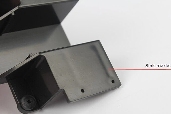
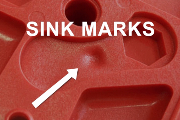
Sink marks in injection molded parts occur during the plastic injection molding process, where thermoplastic resin is melted, injected into a mold, cooled, and solidified to form the final product. Generally speaking, these sink marks will appear in the thicker parts of the part, and these defects are mainly caused by the following reasons:
Differential Cooling Rates:
One of the most common causes of sink marks is the uneven cooling of the material inside the mold. Thicker sections of a part cool more slowly than thinner sections. As a result, the material in the thicker areas takes longer to solidify, leading to depressions or dent marks on the surface.
Inadequate Material Packing:
Sink marks can occur when the molten plastic material does not fully pack or fill the mold cavity, particularly in thicker regions. Incomplete packing can leave voids or gaps in the thicker sections, which later collapse as the material cools and contracts, causing depressions.
Thick Wall Sections:
Parts with varying wall thicknesses are more prone to sink marks, especially in areas with thicker walls. The excess material in these sections may not cool uniformly, resulting in variations in surface finish and the appearance of sink marks.
Insufficient Holding Pressure:
Low holding or packing pressure during the injection phase can lead to sink marks. Adequate pressure is essential to ensure that the material fully fills the mold and packs evenly into all areas, including the thicker sections.
Gate Location and Timing:
The location of the gate, where the molten material enters the mold, can affect sink marks. If the gate is sealed too early, before the material fully reaches the thicker sections, it can result in depressions. Adjusting gate locations and timing can help mitigate this issue.

Strategies for Solving Injection Molding Sink Marks
Resolving injection molding sink marks requires careful consideration of various factors during the molding process. The choice of which technique to use depends on the specific part design, material, and production requirements. Often, a combination of these techniques and careful process optimization is necessary to effectively resolve injection molding sink marks and produce high-quality parts.
To address sink marks, consider the following strategies:
Adjust Mold Temperature:
Lowering the mold temperature can help mitigate sink marks. By cooling the thicker sections of the part more quickly, you can reduce the differential cooling rates between thick and thin areas. However, be cautious with this approach, as it can potentially lead to other issues like distortion.
Increase Holding Pressure:
If sink marks result from low pressure in the mold cavity, increasing the holding or packing pressure can be effective. The pressure of the molten plastic being injected into the mold has a significant impact on thermal and mechanical stresses. Adjusting this pressure carefully can help alleviate sink marks, but it must be done with precision.
Extend Holding Time:
Increasing the holding time encourages more uniform cooling. However, the effectiveness of this technique depends on the location of the gates in relation to the thicker wall sections. It also relies on ensuring there is enough time to fill all areas of the cavity before the gate freezes off. Balancing parameters such as pressure, injection speed, and holding time is crucial to prevent molded-in stress.
Reduce Wall Thickness:
Modifying the part design to reduce the thickness of the thicker wall sections can promote faster cooling and decrease the likelihood of dent marks.
Reposition the Gate Location:
Incorrect gate placement can lead to premature gate sealing, resulting in sink marks. By redesigning and relocating the gates, you can adjust the timing of gate closure to eliminate dent marks.
Use Ribs or Structural Features:
Incorporating ribs or structural features in thicker sections of the part can help distribute material more evenly during the molding process. This can reduce the likelihood of sink marks.
Optimize Material Selection:
The choice of plastic material can impact sink marks. Some materials are more prone to dent marks than others. Consult with material experts to select a resin that is less susceptible to sink marks for your specific application.
Design for Manufacturability (DFM):
Employing design for manufacturability (DFM) principles during the initial part design phase is very effective. Working with Sungplastic, our experienced engineers can help you analyze your design, run simulations and make adjustments to minimize sink marks and other potential issues.
Utilize Mold Flow Analysis:
Mold flow analysis software can simulate the injection molding process, helping identify potential dent mark locations and other defects before actual production. This allows for adjustments to be made in the mold design and process parameters.
Post-Molding Processes:
In some cases, secondary processes like sanding, painting, or heat treatment can be used to address sink marks after molding. However, these processes may add additional cost and complexity to production.
Sink Marks and Design for Manufacturability (DFM)
Injection molding contract manufacturers employ Design for Manufacturability (DFM) principles to preemptively address sink marks during the design phase, which is the most cost-effective stage for intervention. Sungplastic engineers utilize specialized mold flow simulation software to simulate the injection molding process comprehensively, creating 3D simulations of flow, heat transfer, and warpage. During this simulation, we scrutinize the project for sink marks and other issues using a DFM checklist tailored for plastic injection molding. Iterative changes to the design, mold plans, materials, and other variables are made based on simulation results, ensuring the elimination of dent marks and other potential problems.
Shrinkage Rates of Different Plastic Raw Materials
The shrinkage rate of plastic materials can vary significantly depending on the type of plastic, its composition, processing conditions, and the specific geometry of the molded part. Shrinkage occurs when molten plastic cools and solidifies, causing it to contract and reduce in size. Manufacturers and engineers often need to account for this shrinkage in their designs and tooling to ensure that the final plastic parts meet the desired specifications. Here are some approximate shrinkage rates for common plastic materials:
-
- Polypropylene (PP): Typically exhibits a shrinkage rate of around 1.5% to 2.5%. However, this can vary depending on the specific grade of PP and the processing conditions.
- Polyethylene (PE): Shrinkage rates for different types of polyethylene, such as HDPE (high-density polyethylene) and LDPE (low-density polyethylene), can range from 1% to 2%.
- Polystyrene (PS): PS typically has a shrinkage rate of about 0.4% to 0.7%.
- Polyvinyl Chloride (PVC): PVC can have a shrinkage rate of approximately 0.2% to 0.6%.
- Polyethylene Terephthalate (PET): PET has a shrinkage rate of roughly 0.8% to 1.2%.
- Acrylonitrile Butadiene Styrene (ABS): ABS materials commonly exhibit shrinkage rates in the range of 0.5% to 0.7%.
- Polycarbonate (PC): PC typically experiences shrinkage rates of about 0.5% to 0.7%.
- Polyamide (Nylon): The shrinkage rate for nylon materials can vary significantly based on the specific grade, ranging from 0.5% to 2.0% or more.
- Polyethylene Glycol (PEG): PEG materials can have a relatively high shrinkage rate, often exceeding 2%.
- Polyurethane (PU): PU materials may have a shrinkage rate of around 0.2% to 0.7%.
It’s important to note that these are general guidelines, and the actual shrinkage rate can vary based on the processing method (e.g., injection molding, extrusion), part geometry, wall thickness, and any additives or reinforcements used in the plastic formulation. Manufacturers typically conduct shrinkage tests specific to their materials and processes to determine the precise shrinkage rates.
How to Adjust the Mold Tolerances Considering the Shrinkage of Plastic Raw Materials?
Adjusting mold tolerances to account for the shrinkage of different plastic raw materials is a critical aspect of successful mold design and manufacturing. Here are the steps to adjust mold tolerances for different plastic materials:
- Understand Shrinkage Rates: First, have a clear understanding of the shrinkage rates for the specific plastic material you are using. These rates can vary from one material to another, so refer to the material data sheet provided by the manufacturer or conduct your own shrinkage tests.
- Calculate Required Dimensions: Determine the desired final dimensions of the plastic part, taking into account the shrinkage rate. To do this, you’ll need to calculate the “molded” dimensions by dividing the desired part dimensions by (1 – shrinkage rate).For example, if you want a part with a length of 100 mm and the material has a shrinkage rate of 2%, you would calculate the molded dimension as follows:
Molded Part Length = 100 mm / (1 – 0.02) = 102.04 mm
This means that the mold cavity should be designed to produce a part with a length of 102.04 mm, which will shrink to the desired 100 mm after cooling.
- Adjust Mold Cavity Dimensions: Modify the dimensions of the mold cavity to accommodate the calculated molded dimensions. This involves enlarging the cavity to ensure that the cooled plastic part matches the desired final dimensions after shrinkage.
- Consider Draft Angles: Incorporate draft angles into the mold design to facilitate the ejection of the part from the mold. Draft angles help prevent damage to the part and the mold and can also affect the final dimensions.
- Tolerance Stack-Up Analysis: Perform a tolerance stack-up analysis that considers both the shrinkage of the plastic material and other factors that can affect part dimensions, such as machining tolerances and assembly processes. This analysis will help determine the overall tolerance requirements for the mold components.
- Quality Control Measures: Implement quality control measures, including in-process inspections and measurements, to ensure that the molded parts meet the specified tolerances. Adjust the mold or process parameters as needed to achieve the desired results.
- Iterative Testing: Conduct molding trials and measurements to verify that the adjusted mold cavities produce parts within the required tolerances. Be prepared to make further adjustments to the mold if necessary.
- Documentation: Maintain detailed records of the mold adjustments, measurements, and production data. This documentation is essential for tracking changes and ensuring consistency in part quality.
- Optimization: Continuously optimize the molding process and mold design to minimize variations and maintain consistent part quality.
Remember that adjusting mold tolerances for shrinkage is a critical part of the molding process, and it may require several iterations to fine-tune the mold design and achieve the desired results. Effective communication between the mold designer, process engineer, and quality control team is essential to ensuring that the final parts meet the specified tolerances for different plastic materials.
Sungplastic is an experienced mold design manufacturer, we help you identify existing and potential issues and correct them during the design phase through Design for Manufacturability (DFM), designing parts with appropriate tolerances and fits to ensure components can be accurately assemble. Work with Sungplastic to identify potential issues during the design phase and find suitable solutions with the help of our professional engineers and designers. We will closely integrate product design, manufacturing technology and quality control to ensure the production of high-quality and efficient products to help you succeed in the ever-changing market.
Get a free quote and design analysis today.
We’ll reply to you within 6 working hours.
We respect your privacy.
+86 139 2927 4777 (WhatsApp, Wechat)
